Advanced Pump Control for Energy Savings in Intermittent Hydraulic Systems
Many hydraulic systems are only required to deliver flow at pressure during certain stages in a machine cycle. This is even more prevalent in the theme park industry because we need time to reset the show or load and unload guests. Because of how these control systems normally work, most hydraulic systems that move show or ride equipment are expected to be “ready to go” at all times. This drives us toward pressure-compensated pump delivery systems that can come on-stroke quickly and have little or no ill effects of compensating (dead-heading) during the periods when little or no flow is required.
Although this is an advantage for a system that needs to respond quickly, it is not the most energy-efficient design.
Take a look at this situation, and see if you agree:
Equipment:
- A 500-gallon reservoir feeds three 75-gpm variable-displacement pumps of which two run and one is an installed spare.
- Pump compensators are simple-pressure compensators, and the three units have cascaded compensator settings of 1,700 psi; 1,650 psi; and 1,625 psi.
- The manifolds and valving are 75-feet away and drive six hydraulic actuators attached to a 6DOF (six degrees of freedom) motion simulator.
- Each actuator has its own 15-gallon bladder accumulator to assist with large moves at high flows.
Performance:
- Maximum system pressure is 1,700 psi. Minimum pressure for the simulator is 1,200 psi, and a warning message will be received at this pressure.
- Average flow is 60-70 gpm total for the two running pumps.
- Peak flow is about 130 gpm but only for short durations of 2-4 seconds.
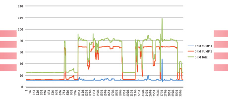
- Parasitic flow when not in flight is 12.5 gpm due to servo valve and actuator leakage.
- Flight time is 4 minutes with 3 minutes between flights.
- Not all simulators fly every 7 minutes. Demand can be sporadic, and some simulators may run only during peak usage and may sit compensated at 1,700 psi for a total of 6-7 hours per day.
Energy Usage:
- An energy-consumption study showed that for 2-3 hours every morning and 1.5 hours every evening, the simulators sat in a compensated state due to maintenance and operational procedures.
- Using amperage data from each electric motor, we learned that during periods of compensation, the “lead” pump was drawing 32.5 amps and the “lag” pump was drawing 19.5 amps at 480 VAC 3 phase (remember that the lead pump is delivering 12.5 gpm all the time to make up for system leakage). This equates to 15,600 watts for the lead pump plus 9,360 watts for the lag for a total of 24,960 watts.
- Multiply this by an average of 4.5 hours per day in a compensated state, and you have 112.3 kWh per simulator per day.
- With six simulators running 365 days per year, this comes out to 245,937 kWh per year at a cost of $0.125 per kWh.
This exercise shows us that running the pumps compensated at 1,700 psi for 4.5 hours per day is costing $30,742 per year. This cost only captures the time in the mornings and evenings that the pumps are compensated. There are other savings to be gained by other incremental controls available on most pumps.
The Solution:
These six hydraulic power units are each controlled by standard PLCs (programmable logic controllers) and already have pressure feedback from the simulator indicating each system pressure. Keeping in mind that the system needs to be ready to fly at a moment’s notice, a new pump control was devised that would perform under the following parameters:
- The ability to unload either pump
- individually
- The ability to bring the pumps back online individually with proportional control
- The ability to shut down and/or start up the electric motor to each pump individually
- The ability to recover from a completely dormant (shutdown) HPU within 30 seconds
We then set out to create control scenarios where the HPU would respond to the simulator’s needs without requiring the simulator control system to make any decisions. Through a communication link between processors, we use information from the motion-control computer to tell us when cabin doors are opened to let people out of the vehicle, when the doors are closed, and when seatbelts are fastened to help us know when we need to be ready to fly.
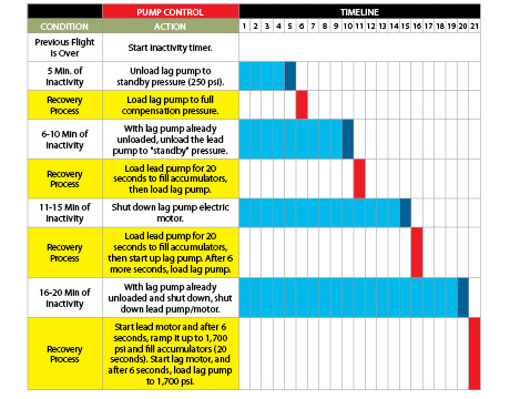
In the event that a simulator is not needed, an inactivity timer will start timing at the end of the previous flight. A normal dwell time between flights is 3 minutes, so at 5 minutes of inactivity, we start a systematic shutdown of the HPU, which takes place in stages. Each of these stages has a different recovery scenario as seen in Fig. 2.
Because we never know when a flight request may come, we need to be able to recover as quickly as possible from any stage of the inactivity process. The recovery times vary from 9 seconds for the first stage to 30 seconds for a fully dormant HPU.
One point to be noted is that at the point of unloading the primary (lead) pump to 250 psi, the entire system pressure drops to 250 psi, as well. The stored oil in the accumulators will start to deplete through all six servo valves at a rate of 12.5 gpm. After 2-3 minutes in this condition, the accumulators will be depleted to 250 psi and will require an additional 22 seconds of recovery time to completely refill them.
Conclusion:
The energy savings that can be harvested from this type of control would have to be verified though data gathering after installation of a prototype system, but conservative estimates tell us that we can save another 155,490 kWh if at least four simulators used the inactivity process four times daily. This is equivalent to $19,436 annually. When added to the $30,742 that can be saved by unloading and shutting down the HPUs at both ends of the day, we find a total savings of $50,178 in yearly electricity costs.
There are many new energy-saving solutions out there that would be good additions to new designs, but sometimes those newer solutions don’t fit well into older systems. In our case, variable-frequency drives were considered to augment our design only to find out the total cost of implementing them was too high and return on investment was over 10 years.
Sometimes when looking for energy savings, you may find that the old tools of the trade that we have had for years, used more intelligently, may save a significant amount of energy.
This kind of pump control may not fit your applications, but pieces of it may be useful in your industry.

