Minimizing Vacuum Leakage
In many vacuum-lifting applications, air leakage is experienced through interconnecting pipe work, porous product materials, or vacuum suction cups that are not properly sealing against the product being handled. Leakage is inversely proportional to the vacuum level of the system, which determines the applicable lifting force of the vacuum suction cups. Increased leakage results in decreased lifting force. Therefore, minimizing or eliminating leaks to provide acceptable and reliable vacuum levels is crucial. This article discusses fundamental methods to achieve that goal.
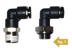 All fluid power systems require the proper selection and installation of applicable components, and vacuum lifting is no different. A factor that is rarely considered when connecting components together in a vacuum system is the thread type used on the interconnecting fittings. Fig. 1 illustrates two fittings, both accepting ¼” tube and connecting to ¼” female-threaded components, such as the vacuum port of a vacuum generator. However, the NPT male thread shown on the left relies on a thread sealant and a certain torque tightening to ensure an air-tight seal, whereas the BSPP (G) thread on the right virtually guarantees an air-tight seal as it uses a flat-face O-ring, which compresses against the female-threaded body face.
Given the relatively low air pressure and consequent safe nature of vacuum “pressure,” there is a tendency to overlook the use of suitable parts installation techniques. If there is a vacuum leak, unlike with compressed air leakage, it is rarely audible and certainly cannot be felt by hand. It is important to use vacuum-rated components and to assure each connecting piece is sealed completely. A vacuum leak may not pose danger to machine operators, but it can certainly affect the performance of an application.
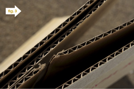
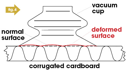
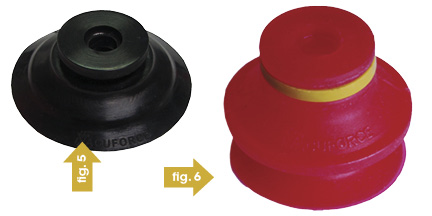
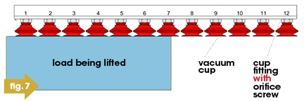
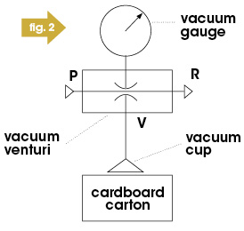 Using a vacuum cup on a rough or uneven surface usually means certain vacuum leakage. As shown in the schematic in Fig. 2, a vacuum cup is placed against a corrugated cardboard surface. The first consideration is the vacuum cup choice. Corrugated cardboard might appear flat, particularly if it’s a new carton, but in fact, as shown in Fig. 3, corrugated cardboard is made of three layers of paper. When cardboard is handled by vacuum cups, the surface deforms, as shown in Fig. 4. This ripple effect determines the vacuum cup choice. Fig. 5 shows a flat 60-Durometer nitrile rubber vacuum cup, and Fig. 6 shows a single bellows 40-Durometer silicone cup. For this application, the bellows cup, as shown in Fig. 6, is the better choice since the bellows design can accommodate the ripples in the surface due to the smaller web thickness (distance between inner and outer diameter of sealing lip) and the added benefit of compensating for height differences when picking from a varying height stack. This results in reduced leakage and better seal on the cardboard. Referring back to Fig. 5, the harder, flat cup will not provide the same results.
As is common in applying vacuum pumps and suction cups, the saying “the bigger, the better” unfortunately is often used in choosing vacuum pick-and-place equipment. This can be far from true when dealing with vacuum leakage. Consider the aforementioned example of handling a cardboard carton. Let’s assume a test. We’ll use two identical styles of cups but with different cup diameters of 3 inches and 2 inches using the same vacuum generator. The 3-inch cup measures a vacuum level of 30% (-30kPa), whereas the 2-inch cup measures 80% (-80kPa) due to more porous cardboard surface area leaking. Which cup is the better choice?
Lifting Force = Cup Area x Vacuum Level = πr2 x Patm x %Vacuum
3-inch Cup: π x 1.52 x 14.7 x 0.3 = 31 lbs.
2-inch Cup: π x 12 x 14.7 x 0.8 = 37 lbs.
As shown from the calculations above, the two-inch cup provides a higher lifting force. This occurs due to the smaller surface area and indeed the perimeter of the two-inch cup, which decreases the volume of air bleeding into the system, which increases the vacuum level. Additionally, smaller cups tend to have thinner lips (the web thickness between the inner and outer diameter of the sealing face), allowing for a better seal as it “digs” into the cardboard face. Decreasing the size of your cup does not always increase the lifting force, but in some leak cases, it can. Proper testing should be conducted to ensure the most efficient system is employed.
Another technique to increase vacuum level when leakage is present is to increase the volumetric air flow of a vacuum generator or pump. The higher-flowing pumps will keep up with leakage more efficiently by removing air quicker and compensating for the leakage, compared to a lesser-flowing pump. From a practical standpoint, changing your cup to reduce leakage is easier and much more cost effective than installing and testing a new generator or pump.
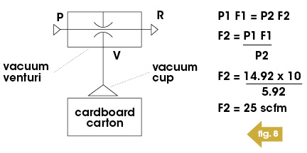
Leakage also occurs when an array of vacuum cups are not all sealed on the product when using a common vacuum source. In Fig. 7, cups 7 through 12 are not sealed against the load. The leakage can be minimized by reducing the size of the orifice in the cup fittings. By selecting a cup fitting with a small orifice, the flow is restricted and less air enters the system. Orifice screws, as shown in Fig. 6, can be installed inside the cup fitting to do exactly that. The cups in contact with the part being handled will maintain their grip as long as the vacuum pump is sized correctly, compensating for the leakage through the cups that are not sealed against the load.
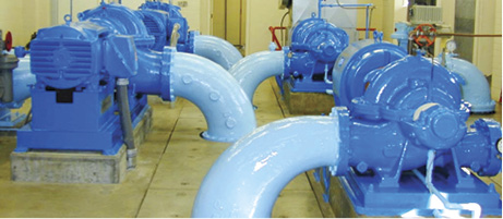
If the vacuum generator is capable of a maximum vacuum level of 27″Hg, and the vacuum level being generated is only 15″Hg with 10-scfm vacuum flow, it is because air is being drawn into the system through the cardboard carton. If you need to create a vacuum level of 24″Hg, what size vacuum generator do you need to overcome this leakage?
Experience has shown that a formula similar to Boyle’s law can be helpful in determining the answer. By substituting flow for volume, we would say that,
P1F1 = P2F2; where
P1 = existing pressure (vacuum level absolute)
P2 = desired pressure (vacuum level absolute)
F1 = flow from existing vacuum generator
F2 = flow needed
Important! The vacuum level MUST be in an absolute measurement.
So,
P1 = 14.92″ Hg(a) ( 29.92″ Hg – 15″ Hg),
P2 = 5.92″ Hg(a) (29.92″ Hg – 24″ Hg)
F1 = 10 scfm
V2 = ?
V2 is what we want to know. Transpose this formula, and you have the calculation shown in Fig. 8. As the calculation demonstrates, the vacuum generator needs to increase to 25-scfm vacuum flow, which is a factor of 2.5 compared to the original 10-scfm unit. This simple calculation removes the guesswork and indeed removes completely the unnecessary costs often associated with this type of “trial-and-error” improvement exercise.
This article has covered a number of different techniques to reduce and manage leakage in vacuum-lifting systems. Vacuum-rated components, proper installation, cup style, cup size, pump size, fitting type, and orifice size all play a role. Each application is unique and therefore requires its own approach to a solution, but by employing at least consideration of the aforementioned examples, leakage can start to be minimized from the get-go.
Share this information.
Related Posts


Sponsor

Sponsors