Auto Lube Systems: Lifeblood to Every Machine
By Suresha Saragur Nijaguna, Mechanical Engineer, Graco
Fluid power is a means to an end. Compressed oil or air can transport an astonishing amount of power from one location to another. The end use of this power is usually some large piece of machinery that, increasingly, has to work and cannot go out of service. These large machines, such as combines, excavators, extractors, and rock crushers, require regular lubrication to stay running.
The typical application requires daily application of grease or oil, usually performed by a recently hired entry-level associate. Was every grease point lubricated? Was the proper amount of grease dispensed? Has that hard-to-reach spot ever been greased? These are the questions automatic lubrication answers.
Humans discovered many centuries ago that friction has undesired effects on mechanical machinery. Lack of lubrication leads to higher friction and irritation of mechanical components.
Lubrication is essential in anything from a sliding garage door to a huge bucket-wheel excavator, which has about 500 bearings and joints to lubricate. We can apply grease manually to our garage doors once a year and maintain good performance. But machinery that works 24 hours a day needs lubrication every day or perhaps every hour. An automatic lubrication system is the best solution. As the name implies, automatic lubrication, or auto lube, dispenses the right amount of lubricant to the right place at the right time.
Manual lubrication is expensive and not practical when machines run constantly. The machines would either grind to a halt from the lack of lubrication, or they’d suffer constant shutdowns to apply lubrication. In the case of manual lubrication, the bearings and pins are often overlubricated, resulting in wasted lubricants and potential environmental hazards. Over time a lubricant’s effectiveness diminishes, creating friction and machinery wear.
Alternatively, auto lube is consistent, keeps up with the machine’s production schedule, and requires no downtime intervention by a technician during operation.
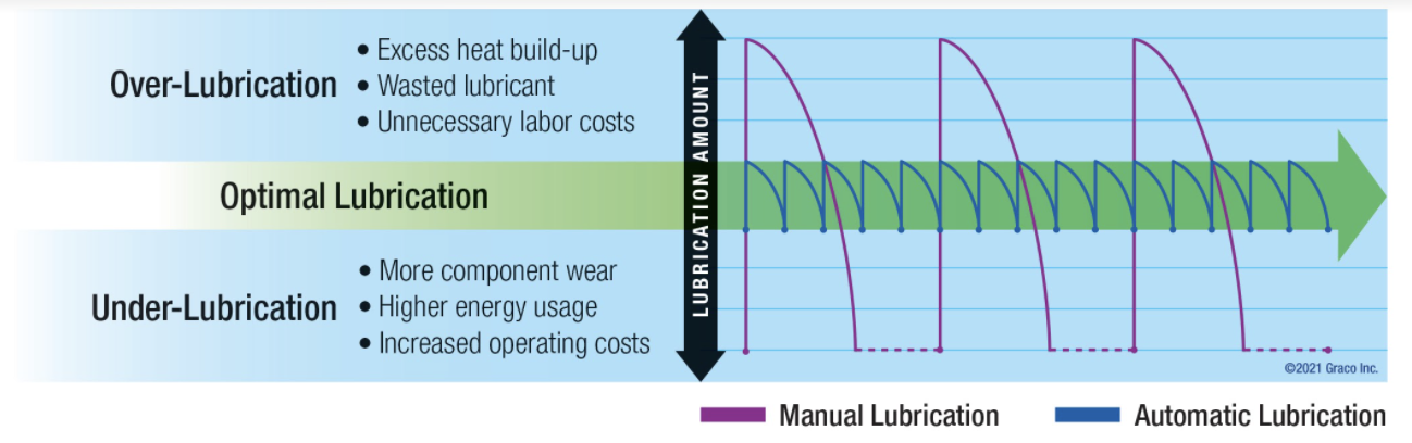
Manual lubrication amounts and intervals versus an ideal auto lube schedule maintaining the appropriate amount of lubrication at each lube point.
Companies over the years have developed complete auto lube systems to meet different machine sizes and styles across multiple industries. Plants that manufacture anything from tires to glass bottles, construction equipment, natural gas compressors, and earthmoving machines that have benefited from auto lube systems.
Basic understanding of the auto lube system is important to select the right one for your application. Most auto lube systems consist of four main items: a pump, a controller, metering devices, and system accessories such as hoses, fittings, and feedback sensors. There are advantages and disadvantages to each system. Let’s look at the differences among the most popular auto lube metering technologies: single-line parallel, series-progressive, and dual-line.
Single-line parallel system
In a single-line parallel lubrication system, a pump pressurizes the main supply line and at the same time fills multiple injectors through a common supply, or “main,” line. Each injector serves one bearing point and can be easily adjusted to deliver a precise amount of lubricant. Injectors operate hydraulically by flow and pressure of the lubricant itself and operate independently of each other.
Precision injectors come in a variety of sizes. Selecting them is based on the system pressure and lubricant volume required for each injector cycle of operation.
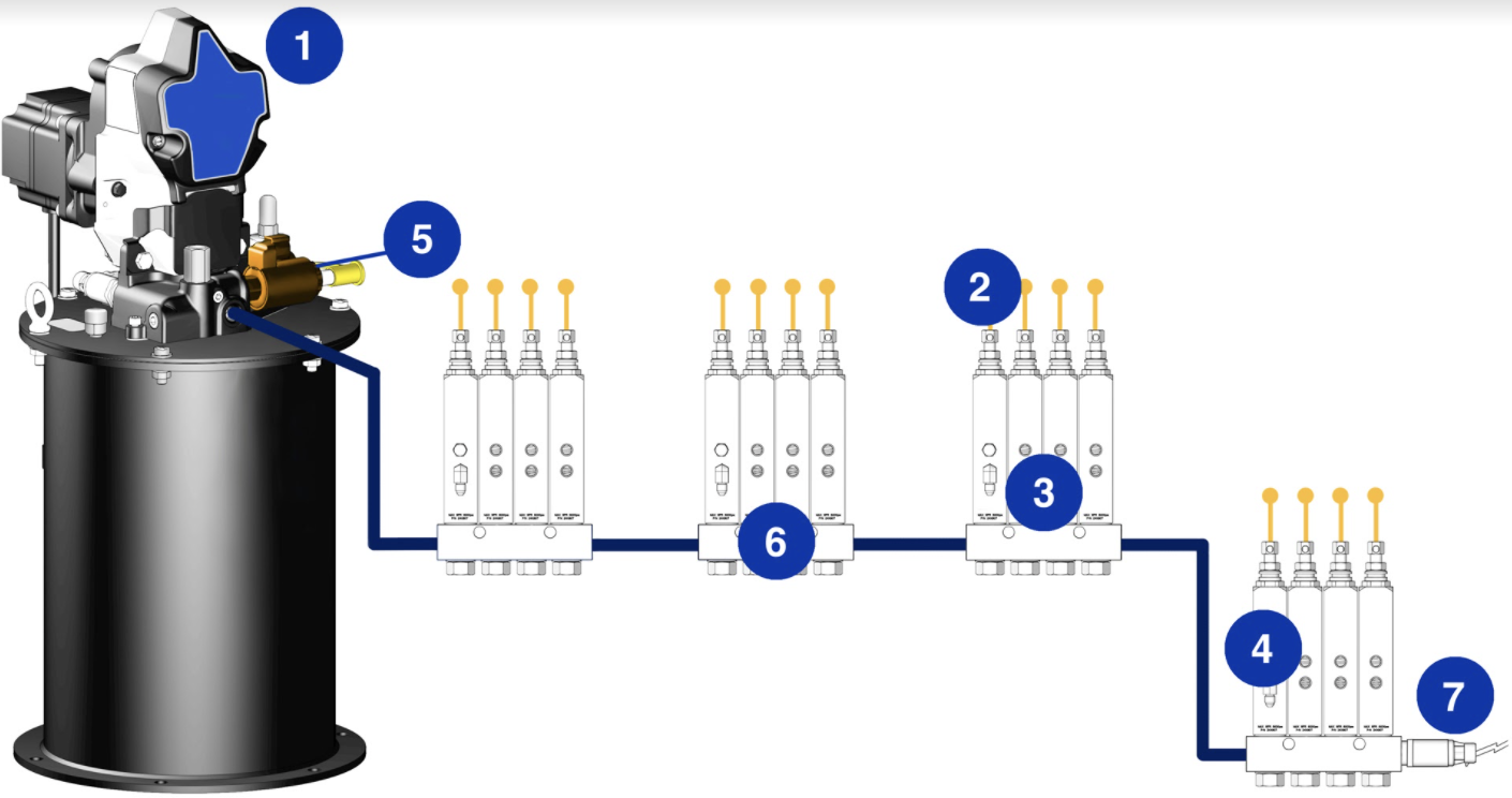
A single-line parallel lubrication system.
- Central lube pump
- Bearings or lubrication points
- Injectors
- Additional injectors
- Vent valve
- Manifold
- Pressure switch
The pump provides lubricant flow and pressure to operate the injectors. Each injector dispenses a preset amount of grease during each lubrication cycle. After operating all the injectors, the pump continues to run and increases the system pressure until it achieves a preset pressure, typically measured with a pressure switch. At the end of the lubrication event, the pump stops and the vent valve opens to reduce the system pressure by allowing the lubricant in the main line to flow back toward the pump tank. As the system pressure reduces, the spring-loaded injectors reset for the next cycle.
The pressure-switch setting and system pressure depend on the length of the system, the number of lubrication points, and the size of the main line to operate the last injector in the system.
It is important to vent the system pressure to reset the injector for the next lubrication cycle. Venting happens by pressure differential in the system. When the vent valve opens, a low-pressure path also opens and allows the pressurized system lubricant to flow back to the pump reservoir. Efficient venting depends on the diameters of plumbed tubes and hoses, the length of the system, the ambient temperature, grade of lubricant according to the National Lubricating Grease Institute, and the temperature-dependent flow rating of the lubricant.
Bearing points can be grouped to mount a set of injectors on a manifold, which is called a bank of injectors.
It is easy to increase or decrease the amount of lubrication from each injector by simply adjusting the piston stroke length of each injector. The injector’s stroke length is adjusted by tightening or loosening an attached screw.
The main advantage of a single-line parallel system over a series-progressive system is that it is easy to add extra injectors by extending the system plumbing.
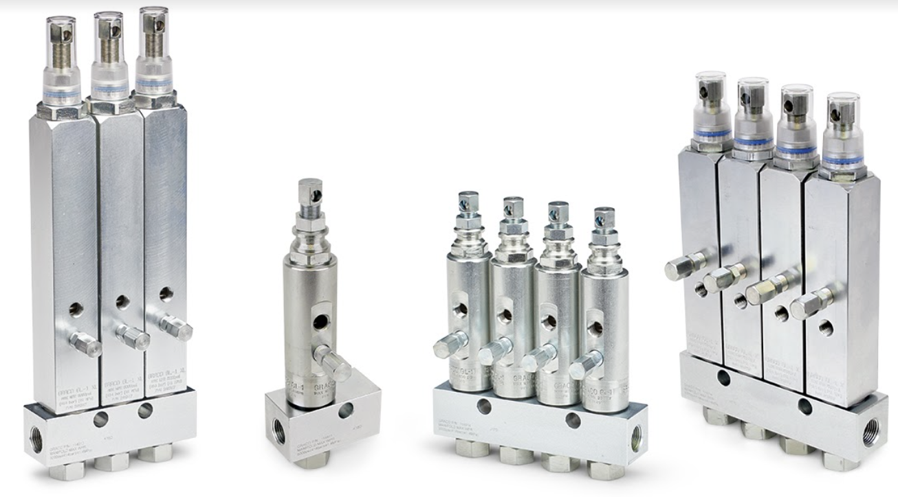
Different size injectors based on output volume.
Series-progressive system
In a series-progressive system, a pump supplies the lubricant through a primary metering valve and multiple secondary metering valves connected to the bearing points. The metering valves are precision machined and are custom sized to each lubrication point in order to deliver the required amount of lubricant. Each piston inside the metering valves is precision fitted by match honing the metal piston to the metal piston bore. These metering valves operate like a series of lock-and-dam channels, where the flow of lubricant opens one lube point at time, moving through the entire system before starting again at the first lube point. The successive and progressive flow path is useful in monitoring the overall system.
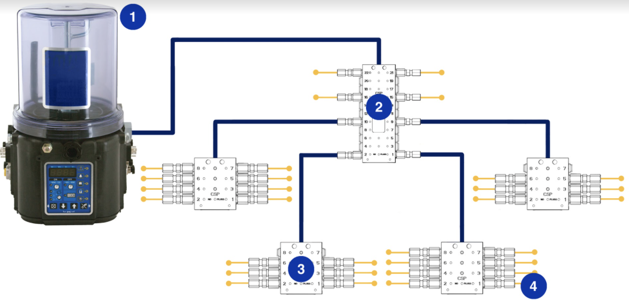
A series-progressive lubrication system.
- Lubrication pump
- Primary metering device
- Secondary metering device
- Bearing point
Bearing points typically require different amounts of lubricant to properly function. Too little lubricant results in high friction, heat, and early bearing failure. Too much lubricant can work against the bearing motion, also creating heat and early bearing failure. The advantage of a series-progressive divider valve system is that each divider can be exchanged with a different-size output valve. Users can fine-tune each grease point for each lube point, from as little as 0.005 cubic inches to 0.08 cubic inches from a single divider valve. Outputs can also be combined to provide additional volumes if needed.
Selection of the central lubrication pump depends on lubrication system size and the number of bearing points requiring lubrication.
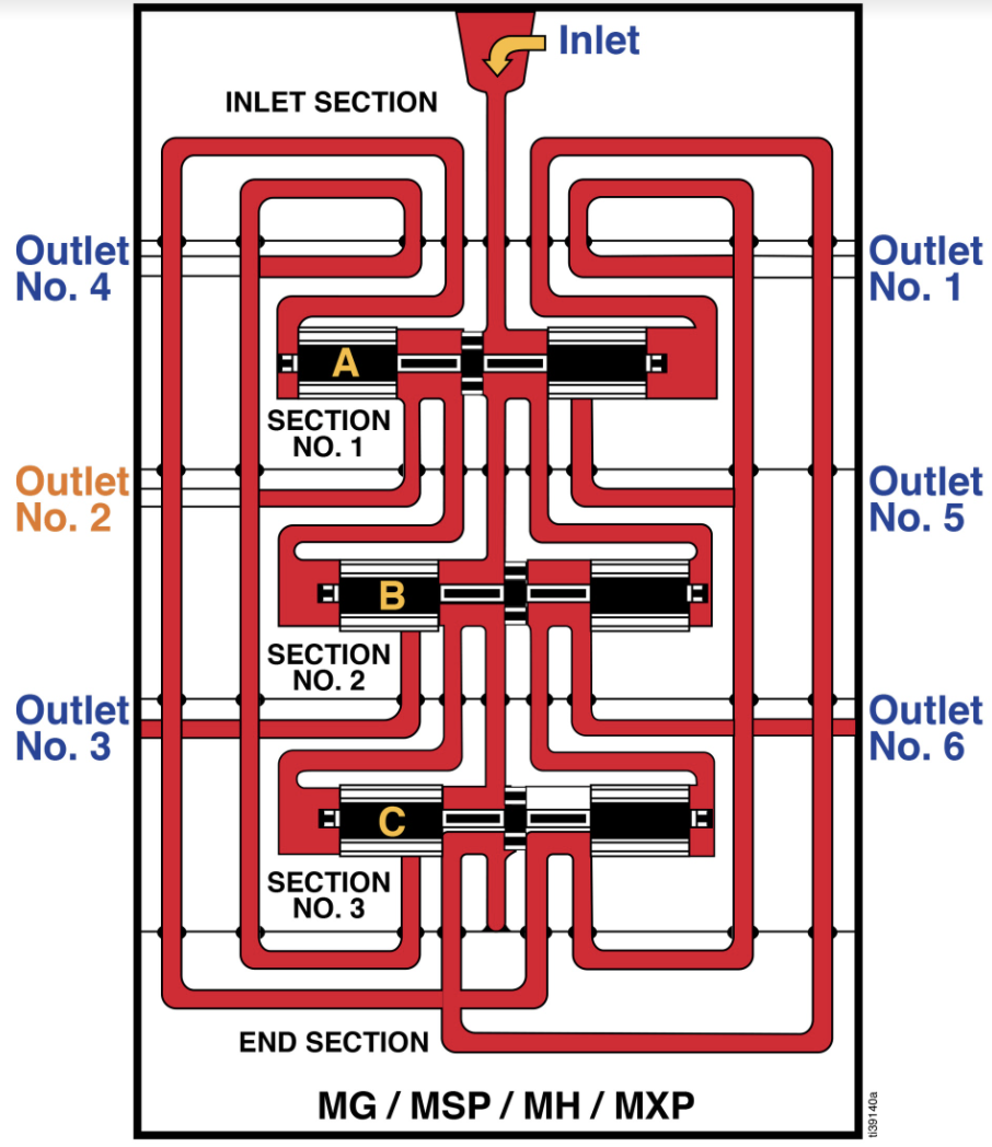
The series-progressive flow path, including the lubricant dispense pathway and complex machining that composes the system.
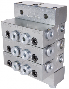
A series-progressive divider valve assembly.
Series-progressive system monitoring
Pumps have either internal or external electronic controllers to program system parameters such as lube intervals, system monitoring, and pump lubricant-level monitoring.
It is important to monitor that the lubrication system is delivering lubricant to the bearings. System monitoring not only helps detect broken and blocked lubrication lines but also can monitor lubricant level in the tank or reservoir.
Recall that the flow of lubricant inside the metering valve is in succession, meaning the movement of each piston depends on flow and movement of the previous piston to complete an entire lubrication cycle for the machine. A blockage at any point in the system will propagate through the rest of the system, allowing for easy and economical monitoring. This monitoring occurs by attaching a proximity switch at the primary metering device to detect the piston movement. If movement does not occur within the set time, the central controller can send out an alarm to alert users of a potential system issue.
In addition to pump selection, it is important to select the right tube and hose size to minimize the pressure drop across the system and also to meet the maximum system-rated working pressure.
Any expansion, extension, or reduction of the system would affect the volume dispensing to each bearing point. Any single outlet failure in the primary valve assembly would affect the downstream system, starving all bearing points.
Dual-line system
A dual-line system has A and B lines that are alternatively used as pressure and vent lines. A pressure line is required to build pressure and actuate the metering devices to dispense the lubricant, and a vent line is required to reduce the system pressure by allowing the lubricant in the line to flow back toward the pump tank. They are connected via branch lines to dual-line metering devices. The advantage of a two-line system is that it can handle hundreds of lubrication points from a single pump station over several thousand feet and can be extended or reduced easily by simply installing or removing additional metering devices. Unlike the series-progressive systems, a redesign of the dual-line system is not required. The pressure line is for building pressure and actuating the metering devices to dispense lubricant, and the vent lines are for reducing the system pressure by allowing the lubricant in the line to flow back toward the pump tank.
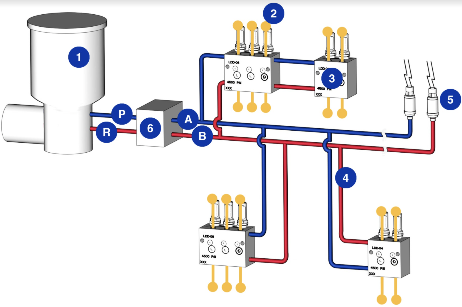
A series-progressive lubrication system.
- Lubrication pump
- Bearings, or lubrication points
- Dual-line metering device
- Branch line
- End-of-line pressure switch
- Reversing valve
A, B: Main lines
P: Pressure line/output line
R: Vent line
Operation begins when the controller/timer sends a signal to the pump to start the lubrication cycle. The pump begins pumping lubricant output through line P, to build up pressure in the first main line A, via the reversing valve, while simultaneously venting the second main line B, through vent line R, via the reversing valve. Once the required pressure is reached, a predetermined amount of lubricant is dispensed by the metering devices to one side of all the metering devices, which is half of the lubrication points.
Once the pressure switch that is monitoring the end of main line A indicates that a preset pressure in the line has been reached, the system is hydraulically closed. The controller shuts off the pump and signals the reversing valve to redirect the lubricant to main line B, and then main line A becomes the vent line.
The next time the controller activates the system, main line B now becomes the pressure line while main line A becomes the vent line. Main line B is pressurized and the entire process is repeated, lubricating the remaining half of the lubrication points.
Auto lube pump considerations
It is important to maintain the lubricant level in the pump reservoir at all times by refilling the pump efficiently without adding contaminants. Refilling the pump can be a tedious task that can possibly introduce contaminants into the auto lube system. Some companies have developed an automatic filling shut-off system that facilitates easy refilling of the pump. This system is purely mechanical and requires no electrical power to shut off the filling operation. The mechanical operation allows the auto lube system to comply with some industry protocols that require 100% power down during all refill operations that include fuel and other working fluids.
Some pumps offer a built-in controller to program the lubrication system with capability to store the history of lube events like lube on-time, pump-low level, and other system alarms. Recent developments in this area include real-time pressure and tank-level monitoring, and Bluetooth programming and monitoring capabilities that can be used with any smartphone with the appropriate app installed.
Share this information.
Related Posts
Roth Hydraulics Accumulators Essential to Bühler Die-Casting Machines

Mobile Market Q&A
Newly Developed: Pneumatic Solution Ensures Model Polyethylene Terephthalate (PET) Bottles

Pascal’s Law and Counterbalance Valves: Part 1
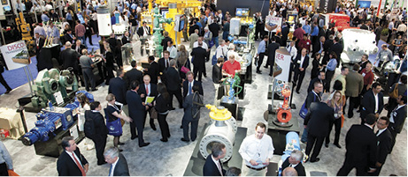
Offshore Technology Conference 2014

Intelligent Pneumatics Move Fluid Power into the 21st Century
One thought on “Auto Lube Systems: Lifeblood to Every Machine”
Leave a Reply
Sponsor

Sponsors
Very well and comprehensively explained. Thank you.