How to Design an Efficient Air Logic System
A Step-by-step Approach That Takes the Guesswork Out of Pneumatic Control
 By Mike Kettering, Technical Sales, Clippard
Electronics have been a dominant control method for decades, but conditions sometimes exist that prohibit the use of electronic controls. For example, magnetic resonance imaging machines emit strong electromagnetic fields that are incompatible with strong ferrous metals and external electronic fields. Strong radio-frequency fields can interfere even with hard-wired electronic controls.
Furthermore, equipment operating in close proximity to explosives or fuels and other volatile fluids must be explosion-proof—a requirement that adds considerable bulk and expense to control components. These conditions may not be the norm, but any one of them can leave control system designers wondering what alternatives are available. This is where pneumatic control provides a surprisingly wide array of solutions.
A Compact Economical Solution
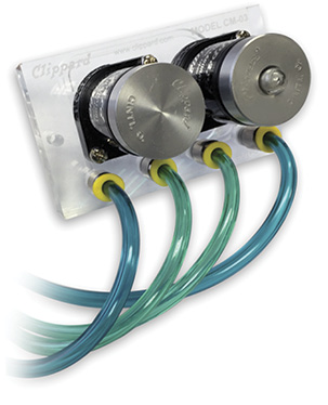
Modular air-logic systems are often a good bet when a compact, economical solution is a must, especially for applications where space is limited. They typically consist of a series of valves mounted onto standard manifold subplates.
Only a few manufacturers offer modular, manifold-mounted pneumatic control systems. For instance, Clippard offers a pneumatic programmable controller—a sequential controller that provides step-by-step system operation. It consists of a clear acrylic manifold for mounting sequence valves and other such components in a compact, efficient package.
The system is designed to automatically generate feedback signals to initiate the next step when an operation finishes. Many types of sensors can generate feedback signals, including limit valves, proximity sensors, pressure sensors, Hall-effect switches, back-pressure cylinder sensors, and manual pushbuttons.
Feedback signals provide positive, safe operation. If no signals are sent (due to a component failure, missing or jammed parts, and so on), the sequence stops and an indicator pinpoints where to troubleshoot. Internal interlocks prevent out-of-sequence feedback signals.
A pneumatic output signal at each step actuates air-piloted devices, including power valves, hydraulic valves, pressure switches, and other components that may control air cylinders. The last sequence valve resets the system to repeat the cycle of operations.
DESIGN BASICS
Modular systems can contain just a few valves or dozens, with many built-in functions to permit a systematic approach to circuit design. As with any control system, it is essential to outline system requirements to save time and reduce the chances of missing a critical step.
Designers must also have a clear understanding both of the sequence of operations (including pressure, temperature, filtration, and other operating conditions) and the control requirements (including manual, automatic, start, stop, etc.). As a final check of circuit operation, consider proper actuation during all conceivable events. This includes startup, shut down, loss of air, panic stops in mid-cycle, restarts in mid-cycle, and control during any other event likely to occur.
Programming Guidelines
 First, label all components in the pneumatic circuit. We recommend labeling each cylinder with a letter of the alphabet, starting with A. The same holds for air motors and other controlled devices. Label the valve controlling the cylinder with the same letter. Label the pilot of the valve that extends the cylinder (or activates a device) with a plus symbol, and the pilot of the valve that retracts the cylinder (or turns off a device) with a minus symbol. Label the limit sensor the cylinder rod strikes with the letters LV (limit valve), the letter of the cylinder, and position of the sensor for extending or retracting. LVA+, for example, would mean the limit valve of an extended cylinder A.
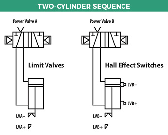
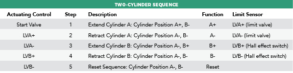
Second, list in detail every sequence of operation. This includes the action or control that initiates a step, what function takes place during that step, and the limit sensor that ends the operation. Note what position all actuators are in for every step. An example of a simple two-cylinder sequence is shown to the right.
Third, select components for the control system. Modular systems offer great flexibility because users can incorporate multiple options when selecting sequence valves. For instance, in the two-cylinder sequence example, five steps (extend and retract the two cylinders plus reset) require five sequence valves.
A basic valve could be used for each step, or you could choose valves with special features. For example, the first two steps could use a valve that provides a sequence reset lock if the start button is held down or if the limit valve LVA+ is locked down. Reset lock means the sequence will not reset to bypass the valve being actuated.
After choosing components, assemble fittings and modular valves into the subplate. Connect the air supply and lines from the limit valves and electrical connections from the Hall-effect sensors to the inlet connections. Finally, connect air lines from the outlet to the air pilots of the power valves.
Changing Operations
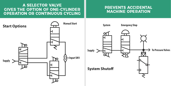
START OPTIONS
If the application demands an input for each cycle of operations, use a pushbutton input signal and a sequence valve that provides a reset lock if the button is held actuated.
If continuous cycling is required, use a selector or toggle valve at the input of the first step along with a valve that permits continuous cycle sequences. For applications requiring choosing between one cycle or continuous cycling, add a selector valve that determines the type of operation.
SYSTEM SHUT-OFF
These controls turn off the main air supply. This prevents harming people or product from accidental machine operation. If the system has large power valves, a piloted three-way main supply valve can control a specific machine section. When electrical circuits are part of the system, an air-piloted pressure switch ensures the system has electric power only if the air is on.
MULTIPLE INPUTS
When two functions actuate at the same time, a piloted 3-Way valve (AND function) ensures both functions are complete before the next step begins.
MULTIPLE OUTPUTS
When two (or more) functions start with the same step, connect the output from that sequence step to both power valves.
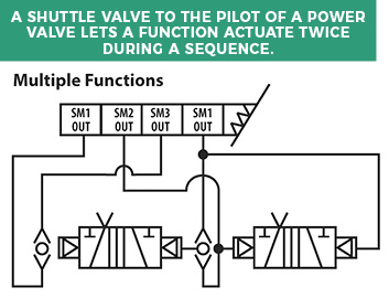 MULTIPLE FUNCTIONS
Functions that actuate twice during the sequence call for the system to connect a shuttle valve (OR function) to the pilot of the power valve.
DELAYS
Applications requiring a delay before a step can use a delay-in module between the limit.
RESET
This control, when actuated, returns the sequence to the start position. Reset can also place power valves in a home position. A reset circuit should only be used when the control is in manual mode.
BACK PRESSURE SENSING
Many air-cylinder applications cannot use mechanical limit valves for sensing because of physical interference, temperature extremes, or other conditions. A method called back pressure sensing indicates cylinder position without limit valves. For example, as a cylinder retracts, it creates a back pressure behind the piston. Restricting exhaust air at the control valve further increases pressure and slows return of the cylinder rod.
This back pressure holds the pilot down on a Normally-Open (NO) 3-Way valve. When the cylinder fully returns, back pressure diminishes at the pilot port of the Normally-Open 3-Way valve, letting a spring shift the valve to send a pneumatic signal to the next step. If the system requires a delay, substitute a delay-out module for the 3-Way valve.
E-STOP
Emergency-stop controls can halt system operations in several ways:
1. Stopping the sequence only
2. Stopping the sequence and relieving pressure from the power valves
3. Stopping the sequence and activating reset controls
A latching mushroom-head button is commonly used for the emergency-stop control because it gives users a positive response when activated.
To request a free Clippard Full-Line Product Catalog, visit clippard.com/link/gwwp. For more information, visit clippard.com.
Share this information.
Related Posts

Lower the Pressure to Keep Your Compressed Air System Healthy

Self-Cleaning Filter Eliminates Downtime for Sausage Co-Packer

The Pressure Is On!

Minnesota West Fluid Power Technology Student Awarded IFPS Past Presidents’ Scholarship

2015 Salary Survey: Looking for Participants
It’s Over: Breaking with Valve Position Tradition
Sponsor

Sponsors