Energy-Saving Considerations and Fixed Pump Unloading
 An energy-saving design strategy must be applied in designing a hydraulic system. This design strategy considers many energy-saving issues that minimize the wasted energy during the operating and idle conditions of the system (that whole topic will be contained in another textbook of this series). For an introductory level, this article will focus on an essential energy-saving issue, which is unloading a pump during the system’s dwell time or idle conditions.
Unloading a Pump that Drives a Single Actuator
Fig. 1 shows the use of a tandem or an open-center directional valve to unload the pump. This simple solution is adequate for a pump that drives a single actuator.

When a tandem-center valve is used, the pump is unloaded and the load is held firmly. When an open-center valve is used, the pump is unloaded and the load is free to move.
Unloading a Pump that Drives Multiple Actuators
If a fixed-displacement pump is used to drive multiple actuators in parallel, a combination of tandem and/or open-center directional control valves can’t be used. That is because, as shown in Fig. 2, the oil is still able to escape to the tank through the central position of the other directional control valve (DCV).
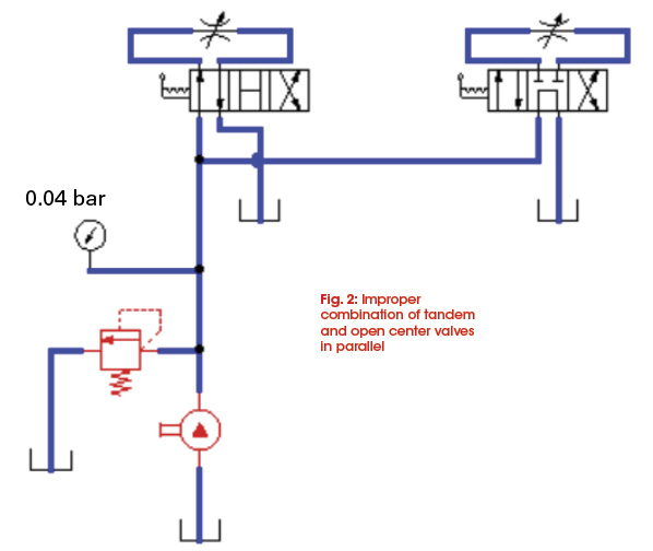
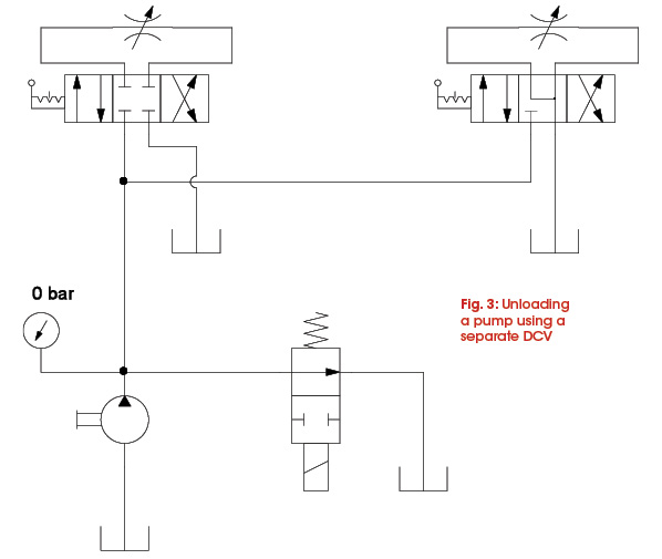
Therefore, for a fixed-displacement pump that is used to drive multiple actuators in parallel, the pressure ports of the DCVs must be blocked. So the valve should be of a closed-center or float-center type.
Fig. 3 shows a fixed pump that drives two actuators in parallel using a closed-center valve and a float-center valve. A 2/2, normally open DCV is used separately to unload the pump. Actuating the unloading valve can be electrically synchronized with the actuation of any of the other directional valves.
Unloading a Pump by a Pressure Relief Valve (PRV) with an Unloading Feature
For large pumps, the previous simple methods of unloading the pump through a direct-operated directional control valve may not be adequate. Therefore, as shown in Fig. 4, a pilot-operated PRV with a built-in unloading valve offers a solution to unload large pumps.
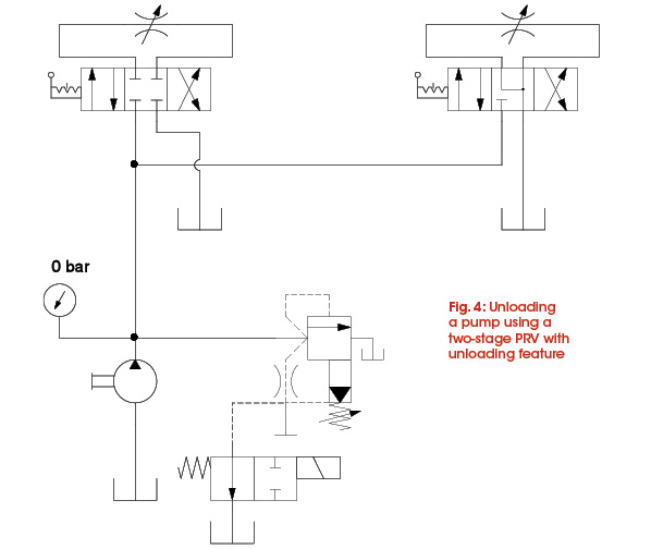
The built-in unloading valve can be selected either normally open, i.e. the pump is normally unloaded, or vice versa, depending on the operating condition of the machine. The idea is to be certain that the pump is unloaded whenever the fluid is blocked by all of the DCVs.
Unloading a Pump by a Pressure-Unloading Valve
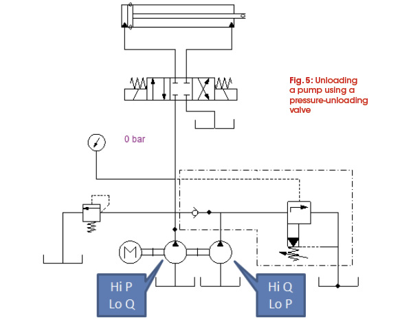
A pump can be unloaded using a pressure-unloading valve, as shown in the Hi-Lo circuit in Fig. 5. In this system, both pumps are joined to advance the cylinder rapidly in the early stage of the cylinder’s extension stroke. When the cylinder touches the work piece and gets into the pressing phase, pressure will increase accordingly. When the system pressure increases, it closes the check valve so that the outlet of the large pump is blocked. Simultaneously, the increased pressure opens the pressure-unloading valve for the large pump to flow back comfortably to the tank.
Unloading a Pump in Mobile Applications
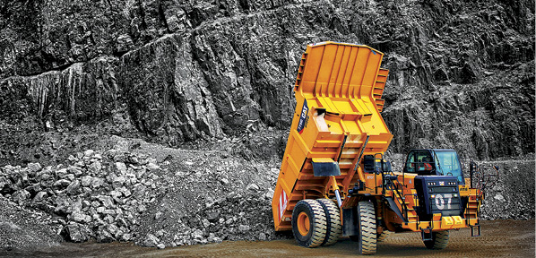
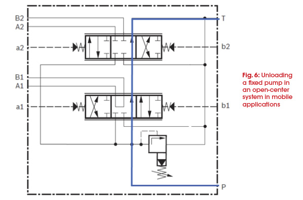
A hydraulic system in a mobile machine could be constructed as a closed-center system or an open-center system. In an open-center system, shown in Fig. 6, when all the spools in the control block are in their center positions, the pump will be unloaded through the open center line.
In a closed-center system, a fixed pump can be unloaded by any way similar to industrial applications. In the system shown in Fig. 7, the pump is unloaded by a solenoid-operated, separate 2/2 directional valve that is assigned as an unloading valve. Actuation of such an unloading valve can be synchronized with the actuation of any of the other spools.
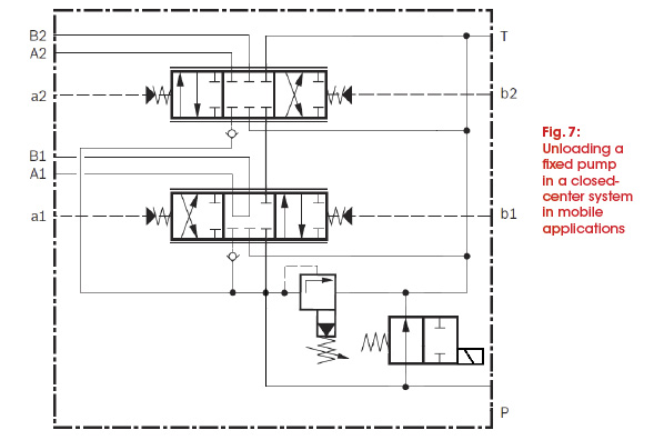
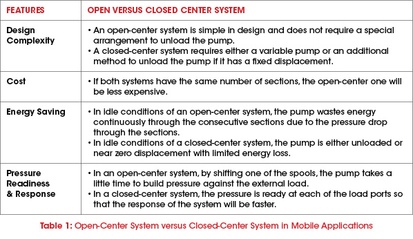
Table 1 summarizes the main features of both systems.
