Handling Large Loads
By Daniel Pascoe
Most vacuum pick-and-place applications involve the handling of small parts such as semiconductor components or food packaging items, which are very common in industry. Less common is the handling of much larger loads such as roofing panels, drywall sheets, diamond plate floors, concrete sewer pipes, and so on. Although these products are all different, they have three things in common: if you drop them, operator injury is possible; machinery damage is probable; and of course you have the cost of damaged product.
In smaller handling applications, the vacuum pick-up and put-down operation takes place within a guarded machinery area. Furthermore, if a low-cost product is dropped, damage to surrounding equipment or the product itself is less likely. In larger handling applications such as molded concrete or wooden panels, however, longer distances are travelled by machinery such as overhead cranes. Therefore, if the product is dropped, the consequences are certainly more obvious and definitely more apparent.
In a good vacuum-handling system, safety components should be included. These components are not expensive, and this article offers suggestions as to how a safe vacuum lifting system can be employed at a relatively low cost.
Self-Closing Valves (Velocity Fuse)
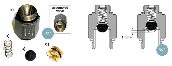
Fig. 1 shows a self-closing valve, which is normally connected directly to the suction cup vacuum port. The valve is made up of the components shown in Fig. 1: a) valve body, b) spring, c) rubber ball, and d) adjustment screw. It is important to understand that this is NOT a check valve. Check valves allow flow in one direction only whereas the self-closing valve in Fig. 1 allows flow in BOTH directions. This is important to allow release of the product being held by the vacuum cup when vacuum is turned off. The arrow on the body of the valve indicates the direction of vacuum flow (towards the vacuum pump).
This adjustable valve is normally set with about 1 mm of spring travel, as shown in Fig. 2. If this valve experiences an “in rush” of air when the vacuum source is turned on, the air flow will push the rubber ball (c) against the seat, closing the valve completely. This will isolate the cup from the rest of the system, allowing the remaining cups in contact with the load to maintain a secure grip.
This type of self-closing valve (or velocity fuse, as it is sometimes called) is a very simple solution to an event where cups suddenly break away from the load being lifted due to damage or poor surface condition.
This valve can also be used when handling different size loads. An array of vacuum cups can be used. The cups that are not in contact with the load will automatically close each time the vacuum is turned on if the cup doesn’t seal against the load surface.
Extra Redundancy
The amount of cups that should be used when handling heavy loads is very simple: as many as possible! The worst thing that can happen when picking something up is to drop it. Dropping a load should NEVER happen if the correct components and procedures are employed. However, what is often asked is, how may vacuum cups should be used? The area in cm² (centimeters squared) of a vacuum cup is the amount it can lift in kg (kilograms) at 100% vacuum or 29.92″Hg (0 Torr or 0 mbar). Therefore, if a vacuum cup measures 100 mm in diameter or 10 cm, then the area in centimeters is 5 x 5 x 3.142 = 78.55 kg or 173 lbs. If you are generating 80% vacuum or 24″Hg, then the holding force is 138 lbs.
Simple enough to calculate. Most manufacturers have this information in their catalogue or cup data sheets, but some manufacturers offer a generous safety factor such as 3:1 @ 70% vacuum. This should be understood when comparing competing brands. The same diameter cup from any manufacturer lifts exactly the same weight.
A safety factor should be employed and as stated before, this factor should be as high as possible to compensate for G force or sudden “jarring” in the mechanical movement of the crane or lifting device. I would always suggest a minimum of FOUR. Therefore, if the load weighs 1000 lb, then use enough cups at the corresponding vacuum level to offer a minimum of 4000 lbs ability.
Careful consideration should be made when choosing between large-diameter vacuum cups compared to a larger number of smaller diameter cups. If the load being handled does indeed weigh 1000 lbs and you employ Ø12″ cups, then the holding force per cup is in excess of 1200 lbs @ 24″Hg. With a safety factor of FOUR, you would only need four cups. If you lose two cups due to damage or poor placement on the load, you have halved the lifting capacity. The biggest threat is the stability of the load if the cups are as shown in Fig. 3. If cup #1 and #2 fail, you most certainly will drop the load as it “peels” away from cups #3 and #4.
The cup system shown in Fig. 4 is a much safer solution offering better stability. This system utilizes ten cups of Ø8″ diameter which at 24″Hg can lift in excess of 550 lbs each. The system has an interlaced dual circuit indicated by the RED and BLUE vacuum lines. If each circuit uses its own dedicated vacuum generator and one fails, the remaining system can still manage the load as the weight is evenly spread.
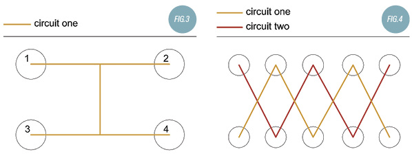
Fig. 3 can lift 4800 lbs and Fig. 4 can lift slightly more, but the lifting capacity of Fig. 4 has more of a chance of succeeding if certain vacuum cups fail, particularly if each cup utilizes a self-closing valve as previously described.
Unfortunately most heavy load-handling systems use a small amount of large vacuum cups. This is of course easier for the machine builder but not as user friendly as a multiple cup, dual circuit system. However, the aforementioned two methods, self-closing valves with dual vacuum circuits, offer significant safety for minimal component cost.
This article is intended as a general guide and as with any industrial application involving machinery choice, independent professional advice should be sought to ensure correct selection and installation.
Daniel Pascoe is President of Davasol Inc, an independent industrial consultant specializing in online brand presence and industrial e-commerce stores, with clients across North America and Europe, one of which is Vacuforce LLC (www.vacuforce.com) a manufacturer and distributor of vacuum components for whom this article was co-written with.
Daniel can be reached via www.davasol.com or directly at dpascoe@davasol.com. Find Vacuforce on twitter.com/vacuforce
Share this information.
Related Posts


Sponsor

Sponsors