Specifying Pneumatic Cylinders – Part 1
Air cylinders are offered in a variety of industry standards. Within these standards, air cylinders come in an assortment of shapes, sizes, and types, as well as with numerous optional features. At first glance, the number of permutations can be a bit overwhelming. The good news is that each pneumatic actuator type and configuration has a place in today’s motion-centric automation environment.
Even though the air cylinder market includes a multitude of standard options, pneumatic actuators are still selected by their ability to perform specific functions. Some examples of common air cylinder applications include the following:
- Opening and closing the gate on a knife-gate valve
- Allowing life-like motion in the animatronics industry
- Diverting goods on a conveyor system
- Raising and lowering rides at an amusement park
- Operating gates to rapidly unload a railcar commodity
- Press operation in the dry-cleaning industry
- Brush movement in the auto-wash industry
Sometimes the job at hand simply falls outside the standard product offering, and only a tailored or custom air cylinder will suffice. The development of custom air cylinders can often be both expensive and time consuming. The two parts of this article outline a step-by-step process to ensure your time and investment are well spent.
1. Two Questions
Properly specifying an air cylinder for any application requires that two questions be answered before moving into the heart of the design. The first question is: What do I need the cylinder to do (what type of work will it be performing)? The second question is: What types of cylinders do I have to select from? As previously mentioned, there are several standard cylinder types available to fit most applications, but often times there are design issues that keep a standard unit from meeting specific requirements. Before charging into the specifics of an application, get a handle on the basics of what you need.
2. Push and Pull Forces
First, determine the force required to properly size the cylinder. When the force is known, you can determine the bore size of the cylinder needed by using the equation: Force = Pressure Available x Effective Piston Area (F=PA) or re-stated Effective Piston Area = Force ÷ Available Pressure (A = F ÷ P).
But this calculation doesn’t consider any inefficiencies. So, as a starting point, let’s add 50% as an efficiency factor. Therefore, multiply the Effective Piston Area (A) above by 1.5 and choose the closest standard cylinder bore size, found by using the equation: Bore = √ (1.5 x A x 4 ÷ π).
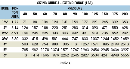
Or we can find the appropriate bore using piston area tables in the manufacturers’ catalog as shown in Table 1. Here, “SIZING GUIDE A” shows the actual piston area and the extend forces obtainable from various air pressures.
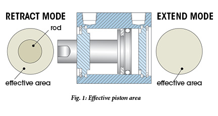
Pulling force, calculated when the cylinder retracts, brings the rod diameter into account. As shown in Fig. 1, air pressure can act only on part of the piston in retract mode because the rod blocks the center portion of the piston. Thus, the effective area for retraction is calculated as an annular ring: piston area minus rod area.
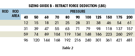
Again, helpful tables from cylinder catalogs provide rod areas to speed calculations of “pulling” force (shown in the sample “SIZING GUIDE B” in Table 2). If you do not have enough pressure to produce the desired force using the preferred bore size cylinder, then you must go to a larger unit. This will affect the package size and may create some space requirement issues, so there is generally a balance that must be achieved.
3. The Cylinder Stroke
Stroke is usually a given in most applications. Decide on it early so you can determine how much of a package size you’ll have when it comes time to address the mounting style.
Okay, so what stroke do you need? Pulling a load might require a 15-ft stroke if you’re closing the door to a large oven. Lifting a stop gate on a conveyor could require only a 2″ motion, whereas pushing a load off the conveyor might require 30″ or more. Staking a rivet wouldn’t require much stroke at all—most likely only a fraction of an inch.
Whatever your task, knowing the stroke starts to define the type of cylinder you’ll need and the envelope size required for mounting it. For purposes of discussion here, we will classify and show examples of four cylinder types by stroke as follows: (a) short stroke, (b) intermediate stroke, (c) long stroke, and (d) specialty stroke cylinders. Note that some cylinders may overlap all of the categories.
Short stroke, compact cylinders: These come in a variety of body styles and have strokes as short as 1/16″ with bores down to 1/2″.
Intermediate stroke: We define these as cylinders having strokes to 36″. After World War II, fast-acting, light-duty automation applications gave rise to compressed air as an alternative to hydraulics. The then-popular tie-rod cylinder construction was copied using aluminum wherever possible to reduce weight and cut manufacturing costs.
Long stroke: We are showing NFPA interchangeable cylinders in this category because their upper stroke limit is 99″. But they are well adapted to applications calling for strokes from 4″ and up (Fig. 2).
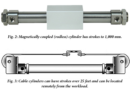
Specialty Stroke (strokes to over 99″): Cable cylinders, made by several manufacturers, are one example of specialty cylinders. As can be seen from the basic drawing in Fig. 3, a clamp can be pulled left or right by a cable attached to the cylinder’s piston. A 15-ft stroke cable cylinder could be used to control the 15-ft oven door mentioned earlier. Because the cable can be any length, the cylinder can be mounted anywhere convenient for the design—directly on the oven or across the room from it, if needed.
4. Mounting
Mounting can be a challenging issue. At this point, it’s time to determine the way you would like to mount the unit and then decide if you have the proper structure and space to do so. This seems like a very basic concept, but failure to plan here can quickly demolish plans. For example, if you would like to flange mount a unit, but there is a fitting in the way of your mounting surface, it may force a redesign to a bottom mount where an additional plate may need to be added.
Okay then, here’s a question: Will the cylinder push a load linearly or turn a crank arm? (The answer determines the type of mount needed for the cylinder.)
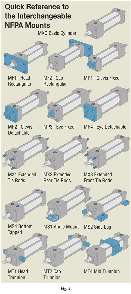
Rigid mounting: For pushing, pulling, or lifting along a straight line, we want the cylinder to be rigidly mounted. We could bolt the cylinder to the equipment, either by bottom-tapped holes or by standing it on end and running bolts into sleeve nut mounts in the end cap. Or we could choose any of the other standard rigid mounts from the Quick Reference to the Interchangeable NFPA Mounts (Fig. 4).
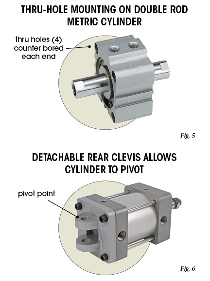
 Rigid thru-hole mounting: Thru-hole mounting is available on many short-stroke cylinder models. It provides counter-bored holes drilled through the cylinder body for easy mounting with socket-head cap screws (Fig. 5).
Flexible mounting: If turning a crank arm, the cylinder would need to pivot. As shown in Fig. 6, a real clevis mount attached to the cylinder would allow it to pivot but restrain lateral motion. Lastly, by attaching the crank to the piston rod with a flexible coupling, the desired motion can be secured.
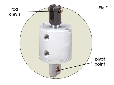
Flexible mounting – short stroke cylinders: Short-stroke cylinders have many of the same mounts as the big boys. Eye mounts, for example, are shown in Fig. 7 on a round-body, short-stroke unit. These mounts also provide a pivot point attachment to allow pivotal motion of the cylinder. To further assist with these types of flexible mounts, rod clevises, rod eyes, and mounting brackets are widely available.
Flexible mounting – non-tie rod cylinders: Most cylinder styles have mounts similar to the NFPA mounts. As an example, trunnion mounts are available on stainless steel body cylinders. Dimensions differ from the NFPA mounts, but they function the same.
Whatever cylinder style you choose, be sure to dig deep into the product catalogs to find the mount best suited to your application.
Reinforce your industry expertise with a Pneumatic Mechanic, Technician, or Specialist certification.
Apply online at www.ifps.org.
For more information: Contact Fabco-Air, Inc. at 352-363-8341 or visit www.fabco-air.com.
Read Part 2 of this article in the Systems Integrator Directory issue.
Share this information.
Related Posts
2016 Skills Competition

How Did You Celebrate?

Self-Cleaning Filter Eliminates Downtime for Sausage Co-Packer
2016 Offshore Technology Conference Attendance Ranks in Top 15
Fluid Power Professional Publishes Historical Fluid Power Book
Automated Drilling Pipe Handler Moves Precisely Due to Electro-Hydraulic Controls
Sponsor

Sponsors