Hydraulic Circuits for Basic Applications
 Fail-safe design strategy must be applied in designing a hydraulic system. This design strategy considers many safety issues that secure the operative and non-operative conditions of the machines. This article series will cover the basic safety and energy-saving requirements of a hydraulic system. It also presents ideas for motion control of a single hydraulic actuator against resistive and overrunning loads, multiple hydraulic actuators in parallel and series, speed control of a hydraulic actuator, boosting speeds of a hydraulic actuator, sequence of operation, and hydrostatic transmissions. In this introductory article, we will focus on the essential safety issues, e.g., limiting the maximum pressure in the system, anti-cavitation checks, and load port checks.
Pressure Limiting
There are two common solutions to limit the maximum pressure in a hydraulic system. The straightforward solution is to use a pressure relieving valve (PRV) with a fixed-displacement pump. The other solution that offers better energy savings is to use a pressure-compensated pump.
The upper left part of Fig. 1 shows an example of a fixed-displacement pump that is sized to discharge 30 liter/min. The pump is protected by a PRV set to 200 bar. At no load, the pump discharges its maximum flow at a negligible pressure.
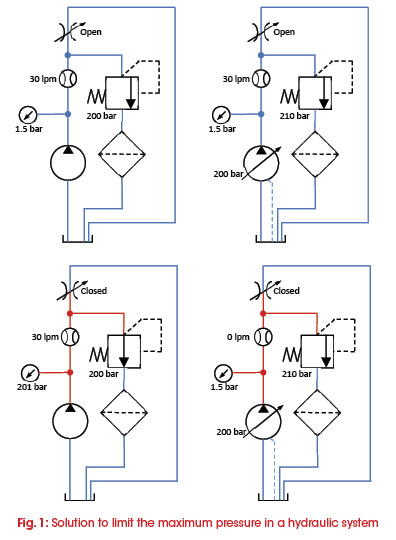 The upper right part of Fig. 1 shows an example of a pressure-compensated pump that is sized to discharge a maximum of 30 liter/min. The pressure compensator is set to a maximum pressure of 200 bar. A backup PRV is used to protect the pump in case the pump controller fails. The backup PRV should be set higher than the compensator of the pump. At no load, the pump discharges its maximum flow rate at a negligible pressure.
The lower left diagram in Fig. 1 shows that, at blocked load, when the full flow of the fixed pump will go through the PRV, pressure is limited to a maximum of 200 bar set at the PRV. In such a case, the full output power of the pump is wasted in the form of heat.
The lower right diagram in Fig. 1 shows that, at a blocked load, the pump compensator fully de-strokes the pump and maintains the maximum pressure so that very little energy is wasted.
The backup PRV should be set around 5-10% higher than the pump compensator. In such a system, setting of the pump compensator versus the backup PRV is a challenge. The backup PRV must be set before setting the pump compensator. The step-by-step setting procedure is as follows:
- Keep the PRV fully opened.
- Keep the pump compensator fully closed.
- Turn ON the pump with the pump outlet blocked.
- Gradually close the PRV to the high setting value.
- Gradually open the pump compensator until the pump pressure is lowered to the required value.
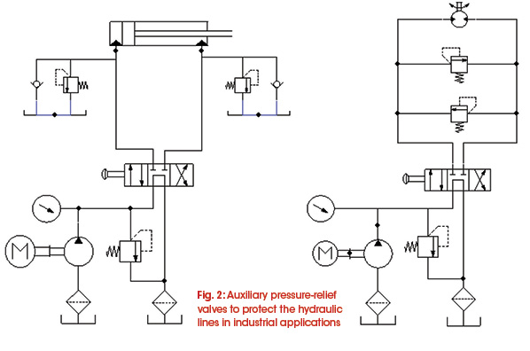
Changing the direction of motion of an actuator, while it is connected to an external load, may result in pressure spikes. If the actuator is cycled very frequently, the pressure spikes fatigue the actuator and hydraulic lines. Fig. 2 shows how auxiliary pressure-relief valves are used to protect the two sides of a cylinder and a motor, consecutively, in industrial applications.
Anti-Cavitation and Load Port Checks
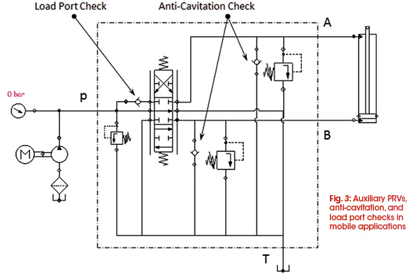
Fig. 3 also shows two auxiliary pressure-relief valves to protect a hydraulic cylinder in mobile applications. The only difference is that, in mobile machines, the pressure-relief valves are built inside the control block. Hydraulic actuators, cylinders, or motors are most likely subject to overrunning load. Therefore, as shown in the figure, two check valves are included in the hydraulic lines to act as anti-cavitation valves. They connect the hydraulic lines to the reservoir in order to compensate for possible negative pressure and to avoid building cavitation in the actuator.
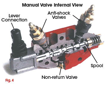
The purpose of the pressure port check valve is to hold the negative load during switching the valve from one position to the other and to prevent possible jerky movement at the load side. Fig. 4 shows a sectional view of a control block that has a built-in pressure port check valve and anti-cavitation valves.
This chapter excerpt is taken from the book, Introduction to Hydraulics for Industry Professionals, Hydraulic Systems Volume 1, 1st edition. Dr. Medhat Kahlil, Ph.D., CFPHS, CFPAI, is director of professional education and research development, Applied Technology Center, at the Milwaukee School of Engineering (MSOE). The book is distributed for free to MSOE seminar attendees.
Share this information.
Related Posts

Animatronics – Shut-off Valve Ensures Safety of People and Equipment

Predict a Profitable Future with IFPS Certification
Servo Valve Design for Faster Response and Low Contamination Susceptibility in Motion Systems

How Smart Hydraulic Equipment Improves Performance

Supersize Me: How a Hydraulic Cylinder Amplifies Its Fluid

2015 Off-Highway Directory Listing and Matrix
2 thoughts on “Hydraulic Circuits for Basic Applications”
Leave a Reply
Sponsor

Sponsors
Hello, I wish for to subscribe for this web site to get
most recent updates, thus where can i do it please
assist.
Excellent way of describing, and pleasant piece of writing to take data
on the topic of my presentation subject matter, which i am going to deliver in school.