Analysis of a Hydraulic Oil Failure
I recently conducted failure analysis and a reliability audit on a 300-kilowatt (400-hp) hydrostatic transmission. This hydraulic system was running a synthetic-ester, biodegradable hydraulic fluid, and the original set of pumps failed inside a year.
The system was built and installed by a reputable firm. From a hydraulic-engineering perspective, the circuit was adequately designed and the system well built. But from a maintenance and reliability perspective, there was plenty of room for improvement.
When I arrived on site, one of the first things I noticed was the hydraulic oil appeared dark in the sight glass, whereas the unused oil was the color of light honey. A subsequent check of the oil-analysis reports indicated viscosity was increasing. Suspecting oxidative failure of the oil, I requested acid number and water content by Karl Fischer. These weren’t included in the original test slate.
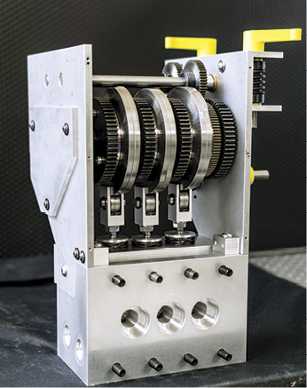
In the meantime, I turned my attention to analysis of the failed pumps. It was obvious the oil had been polymerizing for some time before the pumps failed. Internal components were heavily coated with a gum-like sludge (Fig. 1). These deposits can block lubrication passages, reduce heat transfer, and cause valve stiction.
 The valve plate and cylinder barrel of both pumps exhibited damage from cavitation erosion—another possible side effect of oxidative failure. The oxidation process typically diminishes foaming resistance and air-release properties of the oil, which in turn causes damage through increased air entrainment and gaseous cavitation.
Acid number came back at 9.5 mg KOH/g and the Karl Fischer at 2,200 ppm. For this particular oil, an acid number of between 4 and 5 mg KOH/g is the trigger for an oil change. And although water contamination was much higher than desirable for this application, hydrolysis was ruled out as a significant factor in the formation of the sludge deposits based on the oil manufacturer’s experience.
All the evidence pointed to the fact that this $12/liter hydraulic fluid had suffered oxidative failure well inside 12 months. So with $20,000 worth of hydraulic fluid and $50,000 worth of pumps ruined in short order, my client was understandably wondering what had gone wrong.
Suspecting high-temperature operation as the cause of the accelerated oxidation, I turned my attention to the historical operating parameters of the hydraulic system. As built, the system had a temperature sender installed in the hydraulic reservoir with alarm levels and shutdowns programmed into the system’s PLC. Tests showed this instrumentation to be functioning correctly. But the operators advised the system never had a temperature alarm or shutdown on over temperature.
This didn’t come as a total surprise to me, because the temperature sender was in the wrong location. Let me explain. As many readers would be aware, a hydrostatic transmission consists of a variable-displacement pump and a fixed-displacement or variable-displacement motor operating together in a closed circuit. In a closed circuit, fluid from the motor outlet flows directly to the pump inlet without returning to the reservoir.
Because the pump and motor leak internally, which allows fluid to escape from the loop and drain back to the reservoir, a fixed-displacement pump called a “charge pump” is used to ensure that the loop remains full of fluid during normal operation.
In practice, the charge pump not only keeps the loop full of fluid; it pressurizes the loop to between 110 psi and 360 psi, depending on the transmission manufacturer. A simple charge pressure circuit comprises the charge pump, a relief valve, and two check valves through which the charge pump can replenish the transmission loop. Once the loop is charged to the pressure setting of the relief valve, the flow from the charge pump passes over the relief valve and back to the reservoir.
Apart from losses through internal leakage, which are made up by the charge pump, the same fluid circulates continuously between transmission pump and motor. This means if the transmission is heavily loaded, the fluid circulating in this loop can overheat. To ensure the fluid in the transmission loop is positively exchanged with that in the reservoir and subsequently cooled, a flushing or hot-oil purge valve is installed in the circuit.
When the hydrostatic transmission is in neutral, the flushing valve has no function and the charge relief valve, which is usually located in the transmission pump, maintains charge pressure. When the transmission is operated in either forward or reverse, the flushing valve operates so that the “purge” relief valve incorporated in the flushing valve maintains charge pressure in the low-pressure side of the loop. This purge relief valve is set around 30 psi lower than the charge pump relief valve (Fig. 2).

The effect of this is that cool, conditioned fluid drawn from the reservoir by the charge pump charges the low-pressure side of the loop through a check valve located close to the transmission pump inlet. The volume of hot fluid leaving the motor outlet that is not required to maintain charge pressure in the low-pressure side of the loop vents across the flushing valve purge relief and back to the reservoir.
The important point here and what’s relevant to this case is if the flushing valve malfunctions or is not configured correctly, there is no positive exchange of the fluid in the loop with that in the reservoir. This means the transmission loop can be operating in over-temperature conditions, while the fluid in the reservoir remains relatively cool.
As you can see, in a hydrostatic transmission, the correct location for the temperature sender on which over-temperature alarms and/or shutdowns are based, is in the transmission loop—not the reservoir.
A Failure of Maintenance or Design?
So was this case a failure of maintenance or a failure of design? It could be argued that it’s both. A failure of design in that had the temperature sender been correctly located in the transmission loop, the failure wouldn’t have occurred. A failure in maintenance in that had the early warning signs of oxidative failure of the oil been picked up through observation and better oil analysis test slate selection, the failure could still have been prevented.
ABOUT THE AUTHOR
Brendan Casey is the founder of HydraulicSupermarket.com and the author of Insider Secrets to Hydraulics, Preventing Hydraulic Failures, Hydraulics Made Easy, Advanced Hydraulic Control and The Definitive Guide to Hydraulic Troubleshooting. A fluid power specialist with an MBA, he has more than 20 years experience in the design, maintenance and repair of mobile and industrial hydraulic equipment. Visit his website: www.HydraulicSupermarket.com
Share this information.
Related Posts


One thought on “Analysis of a Hydraulic Oil Failure”
Leave a Reply
Sponsor

Sponsors
The conclusion was that the temperature sensor was in the wrong place to give adequate warning of an “over temperature problem”.
I do not agree and I would make the following points.
1. Taking an oil sample was indeed a very good start in the analysis process. However why did the water content reading of 2,200 ppm not scream of a problem with the cooler?
2. Water content at this level will accelerate the oxidation of the system fluid very rapidly. Alas there is no comment about a cooler in the system nor is it shown on the circuit diagram.
3. A 400 hp system could not function satisfactorily by relying on the cooling of the reservoir alone. taking the figures from the authors other article on “Hydraulic Pumps and Motors” this system would be at best 85% efficient so 15% of the input power could be expected to come out as heat i.e. 60 hp(max). Therefore a heat exchanger is necessary. (It does not hasve to be a water one but if not where does the water come from?)
4. The conclusions drawn to in the discussion do not cover the fact that the hottest fluid is from the drain lines of the motors and pumps and these go directly back to the reservoir so the temperature sensor will see this fluid. Likewise the oil displaced from the low pressure side of the loop arrives back in the reservoir normally via a cooler and often via filter (filter first as hot oil takes less effort to clean than cool oil). Therefore the oil entering the boost/charge pump has to be at a suitable working temperature allowing for a rise in temperature during the working cycle. i.e. this is not the maximum temperature the system will function at but a lower temperature, allowance being made for a temperature rise due to inefficiencies in the circuit.
5. The boost/charge pump is sized to remove/replace somewhere around 20% of the main pumps maximum output. This is often a choice which the system designer can make dependent on the application. The power absorbed by this unit is low and typically 1-3 % of the installed hp.
6. I am somewhat out of date on the latest biodegradable fluids and I am aware there are some very good ones on the market. However I am also aware that one critical aspect of these fluids is over temperature and that once the maximum working temperature is reached there attributes disappear rapidly and failure is very rapid. This was not the case with conventional mineral oils where failure was more progressive and slower. i.e. more forgiving of poor attention to maintenance.
7. If the colour of the fluid, and smell, is used as an indicator of system health you are too late to save the system, it is all over. Or as the comment used to be if it is a chip pan you’ve had it!
8. The reason why the temperature sensors were regularly fitted in the reservoir was one of cost and availability. A sensor in the reservoir is a low pressure unit whereas a sensor in the transmission loop has to be able to take full system pressure and this type of sensor was not as available and cost much more money.
The client now has a major problem as the most difficult situation to rectify is the retrofit of new components into what is a heavily contaminated system, not an easy task.
I would suggest the following list of checks is essential but not comprehensive.
1. Check the oil cooler for suitability of application, location in the circuit and if it is OK then check for water leaks
2. Establish the working/maximum temperature of the fluid being used. The temperature sensor needs to be set such that the temperature in the loop does not reach this maximum figure allowing for a degradation in efficiency over time.
3. If the circuit is as drawn and not a simplification for the purposes then it needs some attention. No filters, coolers, drain lines, etc. are shown. Where these go are critical to safe and reliable. working.
4. As ever the cleanliness figure required for the system needs to be established and a filter of suitable quality selected.
5. Then the tricky job of flushing pipes, hoses etc. starts!!
The only satisfaction the client may have if the supplier is a reputable on is such an early failure is within the warranty period!
I hope my comments may be seen as helpful.