The Next Step in Predictive Maintenance for Mobile Equipment

By Matt Peck, VP Sales & Operations NA, Webtec.
Left to its own devices, most machinery or equipment will sooner or later go wrong. Sometimes it will fail completely and other times it may continue to operate but at a reduced, and probably declining, level of performance. If the machinery needs to be restored to full working condition, rather than scrapped, then either breakdown or corrective maintenance will be required. Where the consequences of a failure are relatively insignificant, then this can be an acceptable maintenance approach. The failure of a bulb in a bedside light or the battery in a tv remote control would not cause too much of a problem and are easily remedied. But a sudden failure of a component on a piece of mobile equipment or agricultural machinery could be much more costly and potentially dangerous. So, on anything but the simplest of machines, reactive or breakdown maintenance is seldom the best approach, both from a cost and disruption point of view. But the fact that many motorists still make use of roadside breakdown services suggests that it may not be possible to avoid it altogether.
Considering the example of a hydraulic pump, an unexpected and catastrophic failure is likely to bring the machine it was powering to a standstill. Without even considering any safety aspects of the failure, such a breakdown is likely to cost significant money due to lost production, potential penalty clauses or spoiled crops. There will also be a cost involved in locating and shipping a replacement unit, supplying or paying for labour to fit it, and probably flushing the system to remove debris from the failed unit. Failure to remove contamination caused by a failed pump is very likely to cause another failure shortly afterwards. So, the sudden, unexpected failures of vulnerable components such as pumps, motors, hoses etc., need to be avoided whenever possible.
The question is, how can such breakdowns be avoided? Preventive maintenance is a technique that has been successfully used to at least minimise unexpected failures even if it may not eliminate them all together. This process involves determining the useful life of a component and replacing or refurbishing it before a total failure occurs. Life estimates may be based upon manufacturer’s data, testing or experience but will also depend very much upon the operating conditions of the component. It’s a procedure adopted by many automobile manufacturers who specify such things as oil changes or cam belt replacement after recommended periods of use.
But the life of a hydraulic pump for example, is not always easy to determine. It will depend upon factors such as the working pressure and duty cycle, the pump drive speed, the type and condition of the fluid (cleanliness and temperature), the pump inlet conditions etc. With a Preventive Maintenance approach, if the life of the pump is under-estimated then it’s likely to be replaced with many hours of useful life still remaining. But if its life is over-estimated then it’s possible it will fail catastrophically before its scheduled replacement time (fig. 1).
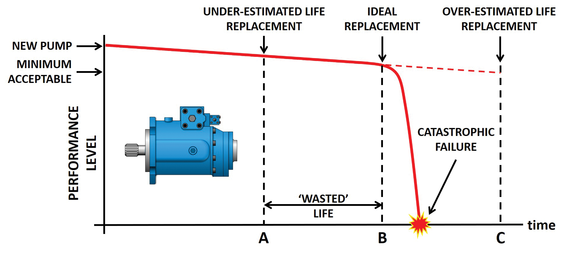
Figure 1 – Preventive maintenance applied to a hydraulic pump
So preventive maintenance is a good approach to adopt where sound lifetime data exists and where operating conditions are predictable and remain within recommended limits.
But as mentioned, the useful life of a pump or motor is not always so easy to determine, in which case a predictive maintenance approach is likely to be more suitable. This involves monitoring the performance of a component so that it can be replaced or refurbished when its performance has dropped to a predetermined level or where there are symptoms of an imminent failure. Probably the best sensor of all is a well-trained and knowledgeable machine operator or service technician. Such individuals are often able to detect slight changes in noise level or spot signs of external leakage from shaft seals for example which can point to an imminent component failure. But modern machinery tends to isolate operators in comfortable, air-conditioned, sound insulated cabs where detecting a machine abnormality is not so easy. Also, the growing trend towards autonomous vehicles removes the operator completely from the machine so machine parameters now have to be sensed by equipment other than human eyes and ears.
How components are monitored or how performance level is defined will vary from one type of component to another. For a cylinder it could be the amount of port leakage in a dead-head situation for example, which would indicate the condition of the piston seals. For a hydraulic motor a vibration sensor could indicate the condition of the shaft bearings and may even be able to determine which particular bearing is starting to fail. A gas pressure sensor on an accumulator could monitor the pre-charge pressure whenever the accumulator was drained of fluid. Hydraulic components which are worn or damaged often generate more than a normal amount of heat so sensing the temperature of a component can indicate when an investigation should be carried out. Excessive heat however can be created in several areas of a hydraulic system, such as an incorrectly adjusted relief valve for example, so further investigation may be required to determine the precise source of the heat. Monitoring fluid cleanliness and water content has been possible for many years by taking fluid samples and analysing them off-line. But on-line fluid condition monitors are now readily available to continuously sense the fluid condition and create alarm signals when it exceeds pre-defined limits. However, in many situations Predictive Maintenance will involve monitoring the two basic components of hydraulic power, i.e., fluid pressure and flow rate.
Monitoring pressure in a hydraulic system is a relatively simple process as it only requires a very small connection from the system to the pressure monitoring device. But unfortunately, many performance losses which can occur in a system may not be evident simply by monitoring pressure alone. For example, a deterioration in pump flow caused by wear or damage will inevitably result in reduced machine performance but may not result in any change of pressure. A pump which is only delivering half of its theoretical flow would still be able to move a load and so generate normal load pressure but would only operate the load at a much reduced speed.
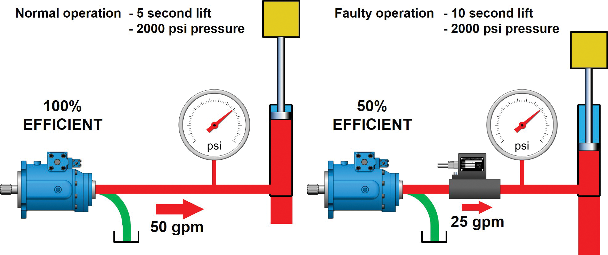
Figure 2 – Monitoring pressure may not reveal the fault
But a slow cylinder speed could be caused by either a failure of the cylinder piston seals or a lack of pump flow, so without further investigation it may not be possible to determine which. A flow meter installed in the pump outlet however could provide enough information to immediately identify which component was at fault, (fig.2).
So, for a hydraulic pump or motor, volumetric efficiency may be a good indicator of the component’s state of wear. Volumetric efficiency involves comparing a pump’s actual flow output with its theoretical output at a specified working pressure, drive speed and fluid viscosity. Manufacturing clearances, internal lubrication passages and control flows mean that even brand-new pumps will have a volumetric efficiency less than 100%, but if a pump’s current efficiency can be compared to that when new and operating under the same working conditions, then a good estimation can be made of how far through its useful life it is or if its condition is deteriorating rapidly.
Measuring system flow rates is not quite as easy as measuring pressure since full bore connections are required to be made in and out of the flow meter, often at high pressure. Also, measuring outlet flow to determine volumetric efficiency at a single point in time may not provide information that is very useful. It doesn’t provide any information about the pump’s performance history, nor does it enable its remaining life to be estimated with any degree of certainty. Wear or degradation of a component does not always occur in a gradual or linear manner and will often accelerate as the wear increases. A predictive maintenance process really requires the component’s performance to at least be monitored at regular, scheduled intervals. This will then provide a history of the pump’s performance over time and enable a more realistic assessment of its remaining life.

Even this approach, however, depends on whether provision has been made to easily connect a flow meter into the system and if the monitoring has been carried out consistently and diligently at the specified time intervals and under the same working conditions. Care must be taken to ensure that measurements are taken at the same pump drive speed, and with the fluid at the same temperature and pressure. This may not always be practical while a machine is operating on-line, especially if the pump is a variable displacement unit when the output flow will be varying naturally. So very often measurements will need to be carried out with the machine off-line so that a predictable and consistent test routine can be carried out on the pump. How often these test routines should be carried out is another factor that will need to be determined. Too long an interval runs the risk of the pump deteriorating rapidly in between tests and a catastrophic failure could still then occur.
An even better procedure would be to monitor the pump’s performance continuously, so that any sudden deterioration in performance could be detected immediately and the appropriate action taken. This then requires a simple, robust flow monitor permanently installed in the system such as the Webtec CTA Series turbine type flow monitor which provides both a temperature and a flow rate output signal compatible with SAE J1939 CANbus communication as used on many vehicles.
The principle of operation of the CTA Flow Monitor is a well proven design which uses a turbine wheel mounted in the flow stream and a sensor which senses the passing of each turbine blade. As flow passes through the flow monitor, the turbine blade spins at a speed proportional to the flow rate. The on-board electronics then convert the sensor pulses into a flow rate signal which can be transmitted via the CANbus signal to the vehicle’s main supervisory control system (fig 3).
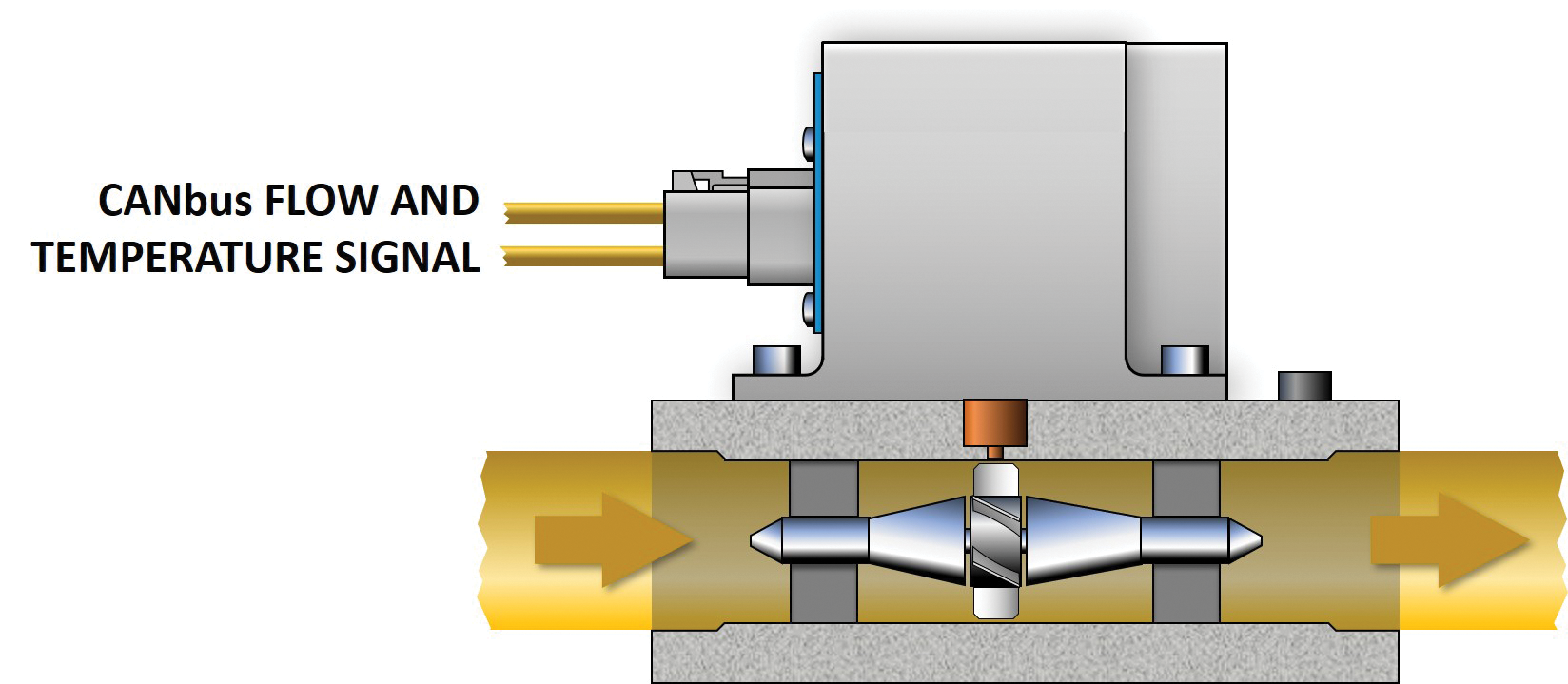
Figure 3 – Flow Monitor principle of operation
The same sensor is also used to monitor fluid temperature which can form part of the system performance evaluation process or, if necessary, used to modify the flow monitor reading to compensate for fluid viscosity changes with temperature.
Combined with drive speed and system pressure sensor signals, a permanently installed flow monitor can thus form an important part of the predictive maintenance process on a vehicle. By communicating directly to the vehicle’s control and monitoring network, on-line performance data can be transmitted to the ‘cloud’ or Internet of Things (IoT) from where it can be downloaded and analysed in real time and appropriate alarms raised as necessary (fig. 4).
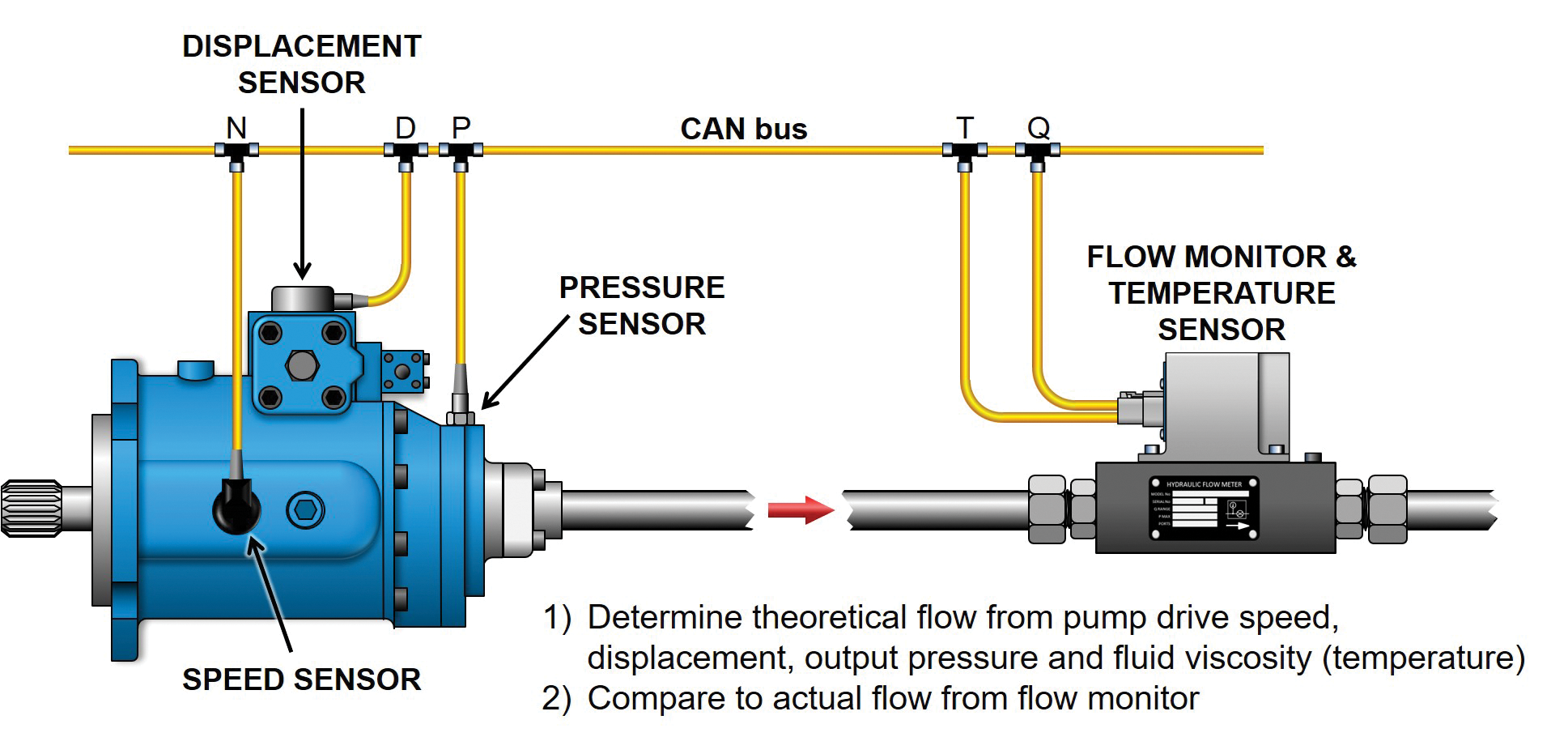
Figure 4 – Using the Flow Monitor to determine volumetric efficiency
While the cost of on-line sensors and their communication network has fallen in recent times, there will still be an initial cost penalty involved in an arrangement as shown in figure 4. However, the additional cost will be substantially less than the cost of the first unexpected breakdown.
Monitoring a piston pump’s case drain has also been used as a means of assessing volumetric efficiency on the assumption that all additional leakage caused by wear enters the pump case and therefore exits via the drain connection. It might be assumed therefore that this would be a suitable location for a permanently installed flow monitor since the flow rate involved would be less than the full pump flow, and at a lower pressure, thus requiring a smaller unit. There are two considerations to be aware of with this approach however, firstly, it may not be correct to assume that all internal leakage passes through the case drain line since leakage direct from outlet port to inlet port can also occur across a worn valve plate for example. Also, some pumps are fitted with a case to inlet check valve so monitoring the drain flow may not give a true indication of the total internal leakage. Secondly, great care must be exercised in adding components to pump and motor drain lines as any additional restriction is likely to raise the case pressure causing additional stress and potential wear on the unit’s shaft seal. Over time it may also create a wear groove on the shaft itself caused by pressure acting on the lip of the seal.

But particularly with variable displacement axial piston pumps, which are probably the most common type of pump used in larger mobile applications, a high case pressure can cause the piston shoes to lift off the swash plate or separate from the spherical end of the piston, both of which are likely to cause a catastrophic pump failure. It must also be remembered that very high case drain flows can be created momentarily due to the movement of the swash plate control piston. Some pumps have case pressure limitations as low as 0.03 MPa (4 psi) and the limitation in many pumps will be less than 0.05 MPa (7 psi) greater than the inlet port pressure. A common cause of catastrophic failures due to piston and shoe separation can therefore be attributed to a high case pressure combined with a low inlet port pressure.
In most applications, monitoring the full pump output flow is the recommended approach. The rugged and compact design of the Webtec CTA Series Flow Monitor make it ideal for on and off-highway vehicles and other machinery where the cost and disruption caused by downtime needs to be reduced to a minimum. Typically, this could include earthmoving and construction machines, agricultural equipment, mining and quarrying machinery, municipal vehicles and cranes and especially autonomous vehicles where reduced performance may otherwise go unnoticed.
Pump output is not the only area where flow monitoring can be useful. The volumetric efficiency of a hydraulic motor can be determined by comparing the motor inlet flow with its rotational speed. On-board speed sensors are common options on many hydraulic motors so by knowing the motor displacement, the inlet flow data from a flow monitor can provide sufficient information to determine the performance level of the motor.
Beneficial as it may be in predictive maintenance applications, there are also other situations where Webtec’s flow monitor may be useful. In difficult environments, sensing an actuator’s speed at the actuator itself can sometimes be challenging where rain, sea-water spray, falling rocks, electrical interference etc. may present difficulties. However, monitoring the fluid flow rate to or from an actuator will give a good indication of the actuator’s speed. The CTA Series Flow Monitors have been specifically designed to be fully EMC compliant, resistant to water spray and steam cleaning, and unaffected by heavy vibration so using a flow monitor may sometimes provide an alternative feedback device when controlling the speed of an actuator.
So, when used as part of a vehicle’s control, safety, or predictive maintenance system, a permanently installed flow monitor combined with state-of-the-art communication capability can provide the next level of productivity improvements and continue the trend towards on-line condition monitoring.
Share this information.
Related Posts


Sponsor

Sponsors