Basic Vacuum Components
Over the last 30-something articles I’ve written for the Fluid Power Journal, I have discussed various product overviews and specific applications offering an insight as to what I regard as good vacuum practice. This article reviews the fundamental components used in typical vacuum applications, offering users a basic understanding to prompt consideration of their selections in a vacuum system.

Vacuum venturis are normally sized based on the amount of vacuum cups being used, the length of vacuum line between the cups and venturi, and, of course, the cycle time required, which will determine the flow of the venturi(s) to enable calculations of vacuum generation time and release. Remember that rarely are venturis selected because of the final vacuum they achieve, but rather the flow they generate. Particularly in vacuum-cup lifting, anything over 15″Hg will be suitable and anything over 24″Hg is a waste of energy. For every square inch of vacuum cup sealing area, you are able to grip about 7 lbs at 15″Hg. That’s more than enough.
If you do not have a vacuum gauge installed in your vacuum system and you have problems with your vacuum system, you are now blind. It’s like driving a car without an instrument cluster: rarely used until you need it. If you were having problems with lifting products, the first question I would ask is, “what is the vacuum level in the system?” If you don’t know, I would therefore be limited in options as to how to proceed, as I would be guessing from the get-go. So, install a vacuum gauge. They cost about $3 and are very easy to find at an industrial outlet.
Vacuum sensors and switches, unlike gauges, are used by the machinery itself to “tell” the PLC on the machinery to proceed with the cycle or stop the cycle once a preset vacuum-level condition has been achieved. The image on the right shows various vacuum-switch models. They all achieve the same objective of vacuum-level condition, but they send different types of signals depending on the IO device being used. Two fundamental types are shown: mechanical/diaphragm and solid state/digital. These two types are shown in the image. The pair on the left is digital, offering exactly the same function but simply a different shape. The two on the right are very simple diaphragm switches that are easy to set and do not require anything elaborate to receive their signal. All of these switches offer the same fundamental value to the user; it’s simply their intended application and user preference as to which one is used.

The aforementioned components are all found in a good vacuum system. Individual component selection is based upon the application itself; however, to understand what should be selected, the venturis and filter should match based on the flow required. The flow rate is based upon the amount of vacuum cups being used and the cycle time required; the valves should be placed as close to the cups as possible; a gauge should be installed near to the vacuum cup(s); and switches should be placed near the gauge. If you start with these basic principles, you won’t go far wrong.

Depending on the application, the various types shown in the image would be selected. The two point-of-use filters are used where smaller single-stage venturis are in place and the filters will be placed directly between the venturi inlet and vacuum cup(s). The inline filter shown is made entirely of plastic with a transparent filter bowl. These are used on larger vacuum-flow applications up to about 180 scfm. The large filter shown on the right is typical of bigger vacuum-pump installations and is available in port sizes for 3/8″ pipe thread to beyond 8″ (200-mm) diameter pipe. Most filters are selected based on the flow capacity that matches the pump or the individual vacuum line; however, if a single venturi or pump of 20-scfm flow capacity is being used on five vacuum cups and each vacuum cup line has an inline filter, then each filter should have a flow rate of 4 scfm. Filters should be sized on flow rate (NOT port size) to ensure that the flow within the system is not restricted.
 Vacuum valves are not as common as they should be in general vacuum applications. They are good conservers of energy by allowing the vacuum system to be fully charged before the vacuum pick-up stage of the cycle. During this “holding” stage, vacuum venturis could be turned off, allowing energy conservation. Vacuum valves can be placed very close to the vacuum cups, offering virtually immediate “grab” of the products. This is of particular benefit in very high-speed applications. Most vacuum valves are electrical solenoid-controlled (as shown in the top left image), although some are available with a pneumatic pilot instead. This type is useful for 100% pneumatic circuits where electrical power is not available or even permitted, such as an oil or gas installation.
There are many different types of vacuum cups, with some of the most common shown in the right image. The most popular type is a single bellows cup (#1), which allows height variances in the load being handled or variances in machine approach distance. This enables the user to set the machinery to an approximate pick-up point unlike when using flat cups, which require a much more accurate placement against the product being handled. Multiple bellows vacuum cups (#2) have the same benefit as single bellows, but the cup is able to lift the product being handled independent of the machine movement. This is very useful for thin-sheet separation, and because of the lesser web width of the cup (difference between external and internal diameter), this type of cup is suitable for plastic-wrapped products, such as food packaging, as the lip of the cup can deform vertically without breaking the seal.

Flat cups (#3) offer less flexibility in the approach stage, but offer much higher mechanical stability when handling products at high speed or when moving product from a horizontal to vertical position (through shear).
Vacuum cups are available in a variety of materials including Nitrile rubber (NBR), which is suitable for general handling including cardboard, steel sheet, and plastic. Silicone is used for high-temperature and low-temperature applications and also the handling of food and food-packaging materials. Polyurethane is very hard wearing and used in continuous and rapid cycle-rate applications. Some vacuum cups made from polyurethane offer a dual duromater (#4) construction, which offers a rigid body but with a soft-sealing lip.
 Most vacuum cups are available with threaded fittings for connection to machinery, but in multiple vacuum-cup applications, level compensators as shown in the right image are used to offer the ability to pick up from varying heights or from surfaces that are not square to the machinery. These level compensators should only be used for vertical-lift applications and shouldn’t be turned through 90º because the bushing, unless designed for this purpose, will wear. Level compensators also offer simple installation through the bulkhead of machinery and end-of-arm tooling.
This article is intended as a general guide and as with any industrial application involving machinery choice, independent professional advice should be sought to ensure correct selection and installation.
Share this information.
Related Posts
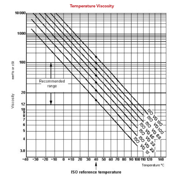
Ensure Temperature and Viscosity Compatibility
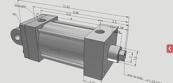
Aignep USA Launches NFPA Cylinder Configurator

Flow Transmitters Enable Remote Monitoring of Flow Meters – Even in Hazardous Areas
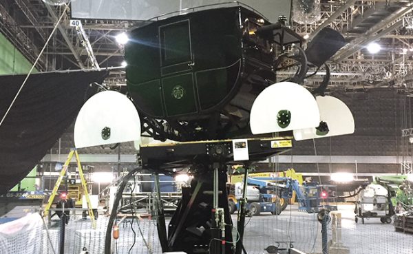
SIKO Position Sensors Used for Movie Special Effects

2015 Off-Highway Directory Listing and Matrix
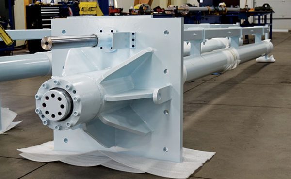
The Wow Factor: Hydraulic Cylinders in Entertainment
Sponsor

Sponsors