IO-Link: A Step Toward Smart Manufacturing
By Sam Skelton, CFPPS Festo Corporation
Control engineers and plant maintenance personnel responsible for machine design and maintenance are continuously inundated with information about new connectivity technology for automation. Although this flood of new ideas and concepts can be overwhelming, it does show that “smart manufacturing” is on its way, a statement most manufacturers would agree with completely. So, what cost-effective, simple-to-implement technology is available now to manufacturers who want to step through the door to smart manufacturing? The answer is IO-Link.
What is IO-Link?
IO-Link is a standardized IO technology for communicating from the controller to the lowest level of automation, such as sensors and actuators. Most importantly, IO-Link is NOT a new fieldbus, but a further development of an existing tried-and- tested, point-to-point communication technology that can utilize unshielded common industrial cabling. IO-Link is already in use in manufacturing automation. With IO-Link, the nightmares envisioned with the implementation of a new system are minimized—if not completely eliminated. You can use the identical fieldbus system your personnel are familiar with, and you won’t have to deal with any new or special cabling on the plant floor.
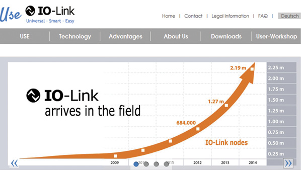
Fig. 1: IO-Link nodes in the field – 2014
Developed in 2009, IO-Link is now in its 8th year of operation, so this technology, which adheres to the IEC 61131-9 industrial standard, is well past the “guinea-pig” stage that manufacturers and end users dread. Current data shows some 2.19 million IO-Link nodes in the field as of 2014 (see Figure 1), and the number of manufacturers participating in, and developing, IO-Link technology continues to expand at a rapid rate. (For a list of companies participating with IO-Link, visit http://io-link.com/en/WirUeberUns/Manufacturer.php?thisID=44. A competence matrix that displays interactively which technologies, products and services the IO-Link member companies provide is available at http://io-link.com/en/WirUeberUns/competencyMatrix_new.php?thisID=43)
IO-Link System Overview
An IO-Link master or gateway transmits all sensor signals to the controller and, conversely, relays control data to the sensor or actuator level. This is how IO-Link integrates every sensor into the fieldbus level. The two-way communication pathway allows for comprehensive ongoing diagnostics and for the automated configuration of parameters for IO-Link devices via the controller.
The IO-Link system is divided into three levels: master, device, and controlled device.
The master level contains the IO-Link master, a module that is commonly manufactured in three forms (part of a pneumatic directional control valve manifold assembly, part of your programmable logic controller (PLC) assembly, or as a stand-alone device). The IO-Link master is the one significant difference in terms of hardware added to a traditional serial communication system. The master facilitates communication to the device level and then indirectly to the controlled-device level. Each IO-Link master communicates over a selected fieldbus or product-specific backplane bus. One IO-Link master can have several IO-Link ports or channels. One IO-Link device can be connected to each port; therefore, IO-Link is a point-to-point communication network, and not a fieldbus.

Festo Corporation IO-Link System
Figure 2 is a Festo Corporation IO-Link system overview for example and reference.
As shown in Figure 2, the Festo IO-Link system allows for the connection of many common devices. At the master level, you see a pneumatic directional control valve manifold assembly (Festo VTSA/CPX), stand-alone IO-Link masters (Festo CECC controller 4 point module and CTEU 2 point gateway module), and, of course, the PLC of your choice. At the device level you see proportional air regulators (Festo VPPM), remote stand-alone IO blocks (Festo CTSL), electric actuator drivers (Festo CMMO), pneumatic pressure switches (Festo SPAU), and pneumatic flow switches (Festo SFAW), as well as additional pneumatic directional control-valve manifolds (Festo VTUG and CPV). At the controlled-device level you see double-acting pneumatic cylinders (Festo DSBG, DSBC, and DSBF), electric actuators (Festo ELGR and EPCO), and pneumatic rotary actuators (Festo DRRD). There are few limits to the devices that can be implemented with IO-Link.
Technical Highlights
IO-Link requires only one three-core cable to integrate most sensors and some valves and actuators. Five wire cables could be needed for other valve manifolds and actuators which require switched load power. Regardless, IO-Link devices are commonly integrated with M12 or M8 connectors for easy connection. Cables can be unshielded and up to 20 meters in length. One cable with power and signal combined will reduce the number of cables in a system.
In principle, any IO-Link master can be combined with different manufacturers. However, double checking compatibility, such as maximum size of user data is definitely advised. One 8 port IO-Link master can support the data transmission of up to 136 sensors. The process data width per port can be up to 32 bytes of IO. A process data transmission rate of 230.4 kBaud is mandatory for any IO-Link master. Process data in a 16-bit length transmits in 2 ms.
IO-Link utilizes a parameter-assignment server function (what some manufacturers call “mailbox function”) for data storage. This function assists in automatically setting the parameters of devices replaced in the field, as well as identifying incorrect item replacements. Non IO-Link devices can be used in a system. However, you will lose the advanced diagnostics and configuration function of an IO-Link device. In addition, diagnostic data is sent over the same line as process data, improving troubleshooting as compared to non IO-Link devices. During production, sensors can be re-parameterized on the fly, thus allowing for the potential to run multiple components on the same line. This same re-parameterization ability allows for spare parts inventory in the plant to be drastically reduced.
Share this information.
Related Posts
Sponsor

Sponsors