Linear Displacement Sensors
The first factors to consider when selecting linear displacement sensors are the mechanical interface, dimensions, contact, noncontact, and environmental factors. Then review the electrical input/output, voltage, analog, A to D, PWM and SSI factors. After high-level choices have been made, lower-level choices must be made based on performance specifications and environmental ratings.
The performance characteristics of linear displacement sensors require a detailed consideration. The following parameters should be cross referenced against application requirements.
Nominal Linear Range
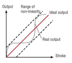
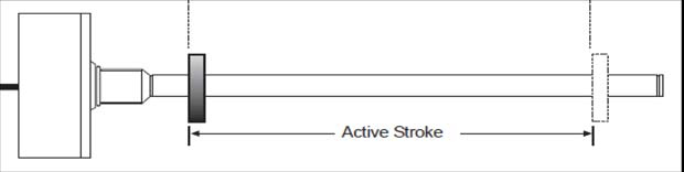
The basic variable in linear displacement sensor selection is the maximum range of core motion, (see figure 1) which produces an analog output of specific linearity. Active stroke is the distance a core can travel from its null position in this linear region.
Linearity Error
A sensor output is a nominally linear function of core displacement within its linear range of motion. A plot of output voltage magnitude versus core displacement is essentially a straight line (see figure 2). Beyond the nominal linear range, output begins to deviate from a straight line into a gentle curve.
Sensitivity, Scale Factor, and Full-Scale Output
Full-scale output is the output with the sensor’s core positioned at full-scale displacement and with its primary excited at a specified nominal input voltage. Sensitivity is usually specified in terms of millivolts output per thousandths of an inch core displacement per volt of excitation (mV/mil/volt) or as volts output / inch /volts input. Sensitivity varies with excitation frequency, which must also be specified. Sensitivity mostly affects the gain required of the sensor’s signal conditioning electronics.
Resolution
Resolution is the smallest core position change that can then be observed in the output. Sensor resolution is essentially infinite. An infinitesimal change in core position will produce an output change. In practice, the limitation on system resolution is the ability of the associated electronic equipment to sense the change in output, which is called the signal-to-noise ratio of the system.
The gradient value (G) is the inverse of the velocity in which a strain pulse moves through the sensor and is typically expressed in microseconds per inch or millimeter. The gradient value is typically found in manufacturer’s literature on a label attached to the sensor itself. The clock frequency (CF) is the frequency of the counter in the customer-supplied interface and is usually expressed in megahertz (MHz).
Resolution (R) can be expressed as 1 / (G x CF)
Example: Assuming a gradient value of 9.000 microseconds per inch at a clock frequency of 56 MHz, what is the resolution in inches?
R = 1 / (G x CF) = 1 / (9 x 56) = 1 / 504 = 0.001984 inches.

Figure 1: Linear displacement sensor.
Repeatability
The ability of a sensor to reproduce the same output for repeated trials of exactly the same input under constant operating and environmental conditions is the single most important factor for sensor selection. Called repeatability, (see figure 3) this parameter is the only irreducible and uncorrectable source of static error in any electromechanical measuring system. Repeatability error is the limiting factor in making any sensor-based measurement.
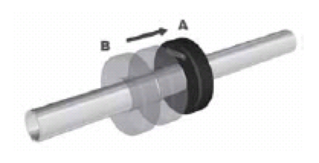
Figure 3: Repeatability.
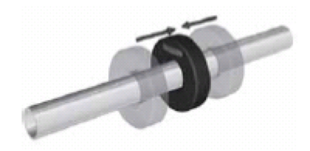
Figure 4: Hysteresis.
Hysteresis
The difference in indicated position (see figure 4) is when the same point is reached from two different directions. Repeatability refers to travel from one direction only, hysteresis is from two directions.For many applications, LVDTs are perhaps the most common type of displacement transducer, their main limitation being overall length.
Magneto-Strictive Transducer
The magneto-strictive transducer is based on a wire connected down the center of a tube known as a wave guide. The object being measured will have a circular target attached with cylindrical magnets built in (see figures 5 and 6). The target and object are free to move along the length of the wave guide. A pulse is transmitted along the wire, and the processor begins counting the time it takes for the pulse to reach the target and generate a return echo (much like radar). The amount of time that elapses from this allows the processor to calculate position, direction, and velocity of motion, which is then transmitted as an output signal in one of several formats, including analog and digital.
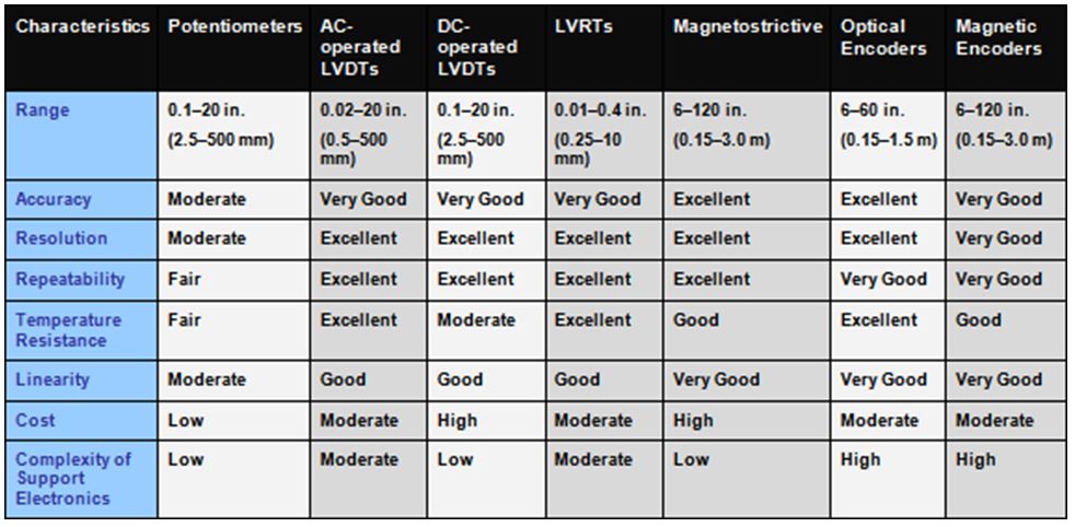
Comparative characteristics of various linear position/displacement sensor technologies.
LVDT
Figure 7 illustrates an LVDT (linear variable differential transformer) and consists of a primary and two secondary coils surrounding a soft iron core connected to the moving component. The primary coil is connected to a high-frequency AC supply and voltages are induced in the two secondaries by transformer action. If the two secondary coils are connected in opposition, then the cores centralized, the induced voltages in each coil will cancel out and produce zero output. As the core is moved away from the center, the voltage induced in one secondary will increase and in the other will reduce. This now produces a net output voltage, the magnitude of which is proportional to the amount of movement, and the phase is determined by the direction. The output can then be fed to a phase-sensitive rectifier (known as a demodulator), which will produce a DC signal proportional to movement, with polarity dependent upon direction.
Figure 5: Magneto-strictive transducer with target.
Figure 6: Magneto-strictive transducer mounted on a cylinder.
Angular Position Transducers
As for linear movement, rotary potentiometers can be used for measuring angular position, but the same problems of wear will still apply and so, again, they are confined to relatively simple applications.
The rotary equivalent of an LVDT is known as an RVDT (rotary variable differential transformer) and is illustrated in figure 8.
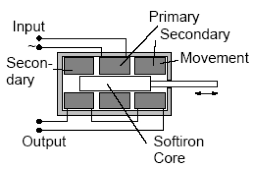
Figure 7: LVDT.
A specially shaped cam of magnetic material is now rotated inside the primary and secondary coils by the input shaft. The profile of the cam determines the amount of magnetic coupling between primary and secondary and hence, as with the LVDT, an output signal is provided proportional to shaft rotation. The limitation, in this case, is the maximum angular movement that can be achieved and still produce linear output, which in practice may be on the order of ±60°.
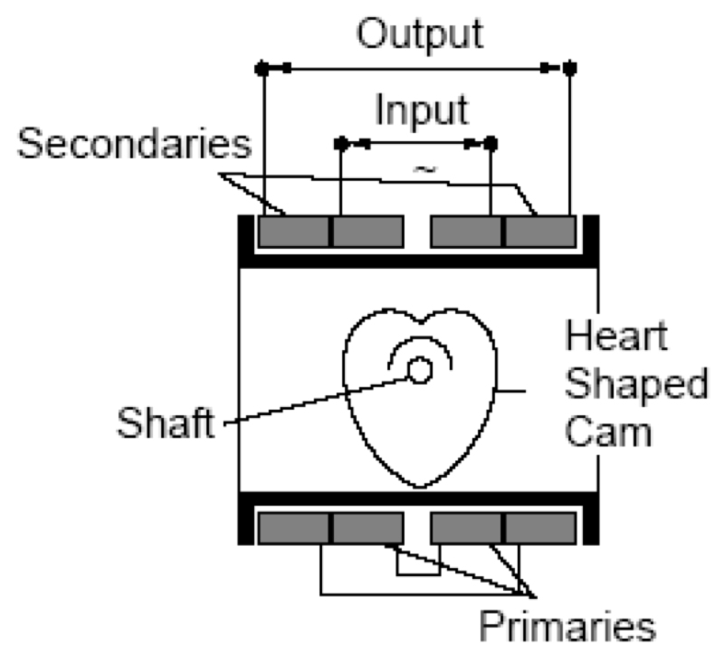
Figure 8: RVDT.
Angular Velocity Transducer
Angular velocity (RPM) is normally measured with a Tachogenerotor. These again may be of several types, but the most common is the DC tacho, which works in a very similar way to a DC generator, i.e., a voltage is produced proportional to the shaft drive speed. •
Share this information.
Related Posts

Test Your Skills: Calculate the Kinetic Energy
The Effects of Pressure Compensated Components on Control Systems
Gas-Charged Hydraulic Accumulators

The “STAMPED” Method

Calculating Intensifier Ratio for Given Pressure and Flow

The STAMPED Method for Selecting Tubing and Fittings for a Metal Tube Assembly
Sponsor

Sponsors