Test Your Skills: Calculate the Kinetic Energy

It is common practice to position shock absorbers to cushion loads attached to air cylinders, rather than to subject the air cylinders to shock loading resulting from end-of-stroke impact. This practice allows sizing the cylinder to move the load and sizing the shock absorber to stop moving the load within the required distance.
In motion control, it is desirable that a load be stopped smoothly and without adverse effects such as rebounding or stress upon the machine or part itself. The speed of the object and mass of the object will determine the best method to accomplish this. When the velocity, mass, and a potential applied force is high, then a shock absorber is the best method to control the deceleration of the object without adverse effects. The kinetic energy that is dissipated is converted into heat energy, so consideration must be given to the cycle rate of the shock absorber to ensure that this heat is taken into account.
Shock absorbers fall within two categories – fixed or adjustable. Fixed and adjustable shock absorbers operate on similar principles to a cylinder cushion in that the deceleration is accomplished by forcing internal fluid over a series of restrictions to provide the damping force required. The advantage of the adjustable shock absorber is that the unit can be fine-tuned over a variety of mass and velocity profiles to achieve precise deceleration. Another possible variant is to use a self-adjusting shock absorber, now offered by several manufacturers. These typically have a range of self-adjustment, so it is still important and necessary to calculate the amount of kinetic energy to be absorbed.
Safety tip: Energy that is input to the shock absorber should be accurately calculated if possible or conservatively estimated for worst case. A shock absorber that “bottoms-out” in service because of insufficient energy capacity will cause the mounting structure of the shock to absorb the remaining energy. This may result in damage to the mounting structure, the shock, or both.
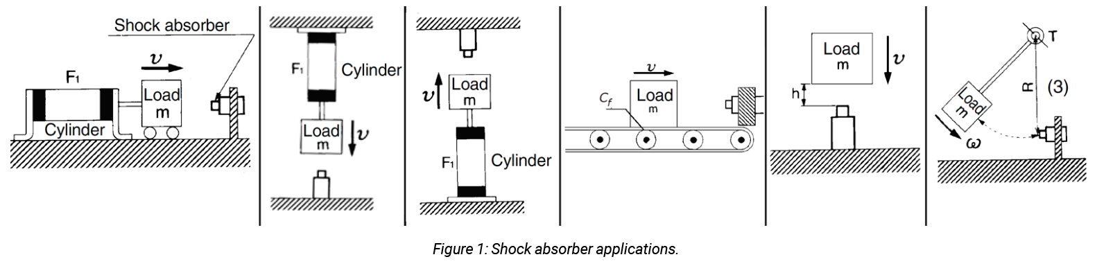
The typical characteristics of stopping a load fit into one of the six scenarios shown in figure 1. There are four parameters that must be known to accurately size a shock absorber:
- Mass to be decelerated m (kg) or (slugs)
- Impact velocity v (m/s) or (ft./sec.)
- Propelling or driving force F (N) or (lb.)
- Number of impact cycles per hour C (#/hr)
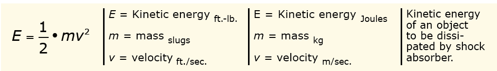
The total energy that will need to be absorbed by the shock absorber is the sum of the kinetic energy and any applied force or thrust energy imparted to the object. The first step in these scenarios is to calculate the kinetic energy of the moving load as shown in this formula.
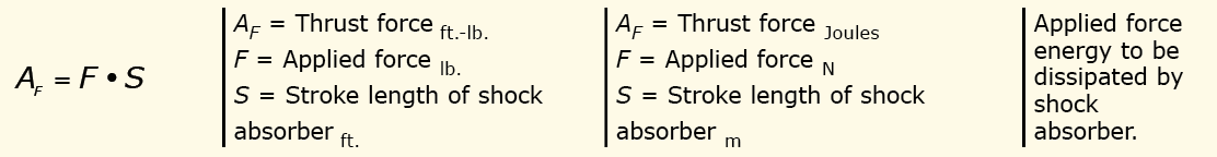
As shown in figure 1, the scenario is moving a horizontal load (by pushing with a cylinder). There is the kinetic energy of the load itself plus the applied force of the cylinder that must be dissipated by the shock absorber.
The equation on the previous page provides for calculating the kinetic energy of the load, and the equation below is used to calculate the applied force. Each of these is additive and the resulting sum is the total energy to be dissipated.
Note: The shorter the shock absorber stroke, the more abrupt the deceleration force that must be taken up by the shock absorber.
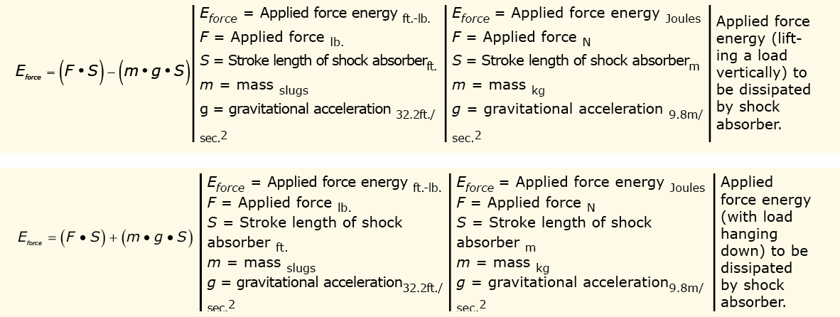
The next two scenarios reflect applications where the load is being moved vertically – either up or down. In this case, not only does the kinetic energy of the moving mass and the applied force, if any, need to be accounted for, but gravity is also at work. In lifting the load, gravity is acting to resist the movement and thus provides somewhat of a damping effect to the applied force. When the load is hanging downward, however, gravity is acting to accelerate the load and adding to the applied force. The two equations below provide for calculations to address the vertical load orientations.
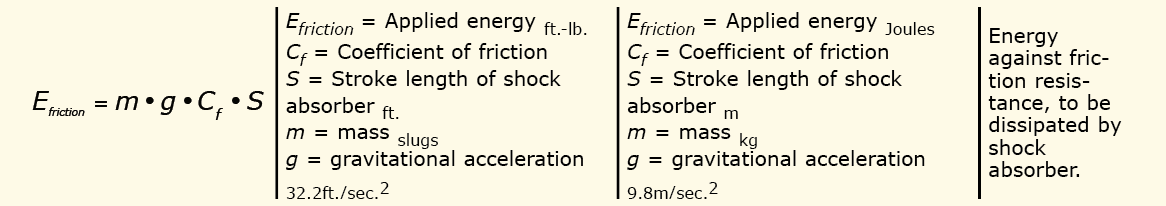
The fourth scenario is one where there is not a constant applied force to the load (a possible transfer line application) but the moving object has kinetic energy and the load moving across a conveyor must overcome a frictional resistance. After calculating the kinetic energy, then the following equation can be used to calculate the additional applied energy.
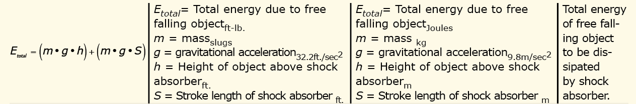
The fifth scenario is the impact from a free falling object. The equation below is used to calculate this and for this scenario the total energy forces are due simply to gravity acting on the mass.
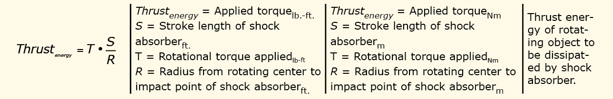
The sixth and last scenario is the total energy due to rotational forces. The total energy to dissipate is the kinetic energy due to the moment of inertia and rotational speed. Additive to this is the propelling force (torque) imparted to the object while rotating, which is calculated using this equation.
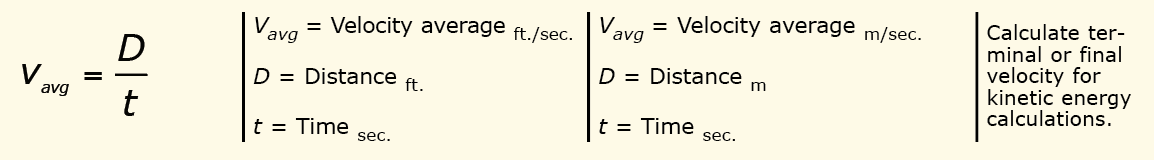
In all the scenarios, it is likely that the actual velocity is unknown but can be calculated based on the distance covered in a set amount of time.
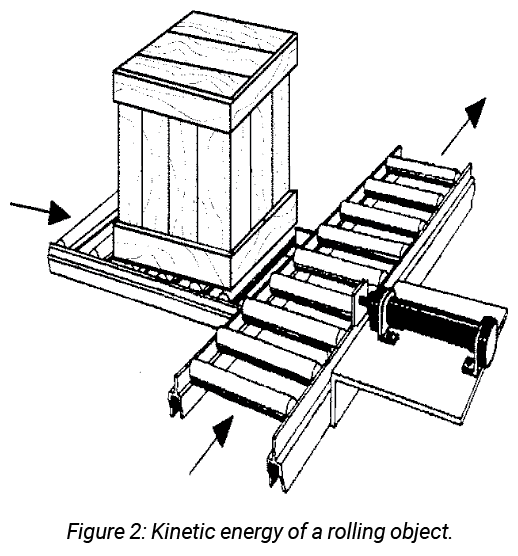
Consider a crate, like that shown in figure 2, rolling into a shock absorber mounted on a conveyor. Since the starting velocity is zero and assuming that the crate accelerates uniformly, the average velocity of the crate may be calculated by the following equations. The average velocity is the distance traveled divided by the time it takes to travel the distance:
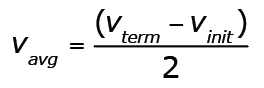
Since the starting velocity is zero, the average velocity may also be expressed by the equation:
Since the initial velocity is zero, the last equation may be rewritten as:
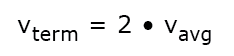
Therefore:
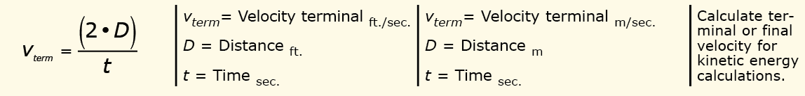
Many manufacturers of shock absorbers use an additional step in selecting the proper one. They calculate the mass equivalent of the entire kinetic energy imparted to an object at the speed of impact. That is calculated using:
An important fact to use when calculating the mass equivalent for a free falling object is that the velocity is due to the gravitational acceleration and height using:
Consider the following example: A crate that has a mass of 100 kg is pushed from one horizontal conveyor to another by a cylinder (not shown but indicated by the arrow). The coefficient of friction of the conveyor is 0.2 and the distance to be traveled is 5 m. The time it takes to travel this is 1 sec. The crate was pushed onto the conveyor by a cylinder and that resulted in an initial amount of kinetic energy of 100 Joules. The shock absorber stroke length is 50 mm. What is the total energy that the shock absorber will need to be capable of dissipating? Of these factors, only the terminal velocity will be an unknown factor in the problem.
Solution: The kinetic energy was given as 100 Joules. To solve for the applied force energy due to the mass moving over a surface with friction, use this equation.
If using shock absorbers that use mass equivalent as a selection criteria, then this equation would
be used:
Velocity was not given but could be easily calculated from the distance and time stated. The me is 2.2 kgs.
Test Your Skills
What is the total energy needed to be dissipated by a shock absorber that is positioned under a vacuum cup that releases a free-falling load of 2.5 kg, 0.01 meter above the shock absorber, and the stroke of the shock absorber is 0.05 m?
a. 0.17Joules
b. 0.67Joules
c. 0.96Joules
d. 1.12Joules
e. 1.47Joules
See the Solution
The correct answer is e.
Share this information.
Related Posts
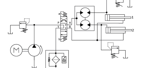
Understand the Function of Hydraulic Components in Circuits: The Application of Pumps and Intensifiers
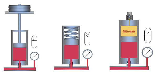
Understanding the Function of Accumulators

Test Your Skills: Electric Flow Control Devices
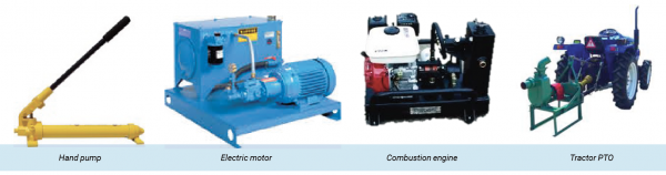
Test Your Skills: The Function of a Prime Mover

Test Your Skills: Sizing and Selecting Vacuum Pads
Test Your Skills: The Application of Fluids
Sponsor

Sponsors