Measuring Marine Tank Fluid Levels with Pneumatics
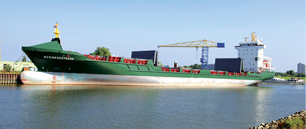
Marine vessels need to reliably and accurately measure fluid levels within tanks aboard their ships for a variety of reasons. These tanks come in multiple sizes and may be used for a wide range of materials, such as
 fresh water/potable water;
- seawater/bilge water;
- black/grey sewage;
- diesel oil, petroleum, gas oil, dirty oil, sludge; and
- heavy fuel oil when in liquid state.
Maintaining reliable and accurate fluid level measurements of these tanks in virtually all working vessels – from ferries to commercial trawlers – is important. A fluid level measuring system or sounding system is used to determine how much fuel or potable water there is onboard a ship, how much fluid is in a storage facility, and even the ship’s draft.
Electronic and Pneumatic Measurement Comparisons
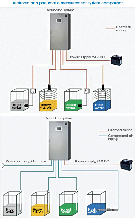
Different methods can be used for tank fluid measurement. Electronic measuring systems use a sensor placed in the bottom of the tank; the sensors are connected by wires to a central PLC and operate like any electronic sensor.
The pneumatic method, also commonly used, is based on well-established physics associated with air pushing on a fluid. Also known as “bubbling,” this method uses air blowing through a fixed tube inserted into the tank. The amount of air varies, but it is typically on the order of 5 to 12 liters per minute (L/min) at 2 bar/29 psi fed from the ship’s standard air supply.
The pneumatic pipes are all connected to a central cabinet, which contains centrally located sensors. The systems measure the counter pressure in the air tube and present this as the actual fluid level in the tank.
There are some advantages to using the electronic method, such as consistent accuracy and direct communications of the sensor readings to the system controller. However, this technology also has certain attributes that can make it more difficult to use and maintain:
- Wiring needs to be run from each tank and is susceptible to interference and breakdown.
- Broken sensors or wiring is difficult and time consuming to trace and replace.
- Sensors and wiring in each tank are costlier on a component basis, compared to bubbling technology.
- Different types of sensors may be required on one ship for different applications based on their sensitivity to the chemicals in the tank (i.e., fuel oil, grey or black bilge water, etc.) or temperature levels, which can range from hot fluids to ice water.
Use of the pneumatic bubbling method presents multiple functional advantages, particularly in hardworking vessels that undergo a lot of wear and tear:
- Proven and rugged technology: piping is relatively easy to install and does not wear out.
- Useable areas include virtually all tank types and applications.
- No maintenance is required in the tank, only in the central cabinet where sensors and the air supply are located.
- Sensor outputs are fully automated, and can be communicated and integrated into shipboard control systems.
- With bubble-type system stops, if there is a power supply/air supply failure at the cabinet, the fluid level can be checked from each individual tank.
- Bubble-type systems do not require maintenance engineers with electronics training or background.
New Advances in Pneumatic Level Measurement
Until recently, the pneumatic method of tank fluid measurement has required a constant airflow through each sounding pipe to obtain an accurate measurement. This could require a significant pneumatic pressure be maintained: to measure 10 tanks, each tank would need between 5 and 12 L/min continuously.
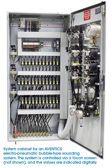
 Pneumatic system providers have recently offered improved pneumatic sounding platforms that provide more efficiency and accurate measurement of multiple tanks. Instead of having a constant flow of air to all tanks at the same time, this new approach supplies air in sequence from tank to tank and checks the pressure inside the bubble tubes per tank intermittently.
Using only one sensor per 12 tanks placed inside the control cabinet, the fluid levels are registered and stored in a database. When the fluid level in a tank is measured, it is recorded in the database. By integrating a highly accurate, self-controlling flow regulator with an advanced processing software platform, the accuracy and reliability of this more efficient method can be assured.
These values are constantly compared with each other, and the average is presented. Since the surface of the fluid in the tank is always in motion, due to the motion of the vessel, this consecutive measurement presents a steadier data sheet. This has proven to be a more accurate and reliable method than constant measurement in each and every tank. As the tank is drained or filled, the surface will change in a direction and the system will capture this level change.
There is virtually no limit to the number of tanks that can be measured; depending on the size of the vessel and the number of tanks to be monitored, sub-cabinets containing the pneumatics and sensors can be distributed throughout the ship and networked via standard data links into a main cabinet, which contains the processing controller and software.
These latest advances enable ship builders and operators to deploy a pneumatic-based tank level measurement system that reduces air flow requirements by up to 85% while still providing highly accurate and reliable measurement results.
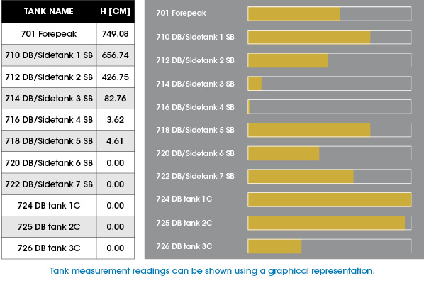
These systems generate real-time electronic measurements that can be easily integrated into most industry-standard Ship Automation Systems; they are designed to furnish necessary data for use in application-specific control systems within the ships, such as automatic valve controls and pump start/stop systems.
These latest developments make pneumatic-based “bubbling” tank level measurement an effective and viable solution: it combines the ruggedness and simplicity of the piping technology with a database-driven solution that reduces airflow requirements significantly while assuring accurate level measurement across the vessel, no matter what tank or fluid is being monitored.

