Military Vehicle Driving Simulator Uses Synchronized Electro-Hydraulic Controls
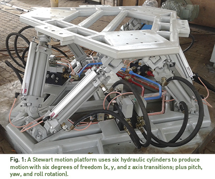
A standard way of building motion simulators is to start with a Stewart platform. Stewart platforms enable movement with six degrees of freedom (x, y, z axis transitions; plus pitch, yaw, and roll rotations). To make a vehicle simulator, one mounts a cab that simulates the vehicle interior on top of the platform. The typical platform is implemented with six hydraulic servo actuators (Fig. 1) driven by an electro-hydraulic motion controller. The nature of a Stewart platform architecture is that achieving the desired motion of the top of the platform in any direction and at any altitude requires moving all of the actuators by a certain amount.
Computing the amount to move each axis can be a mathematically intensive function, and the challenge to system designers is to complete the calculations and affect the motion fast enough to support realistic motion of the platform.
One designer and builder of Stewart platforms for vehicle motion simulators is SERVOCONTROLS & Hydraulics India Pvt. Ltd. of Belgaum, Karnataka, India. The company is involved in design and development of hydraulic and electromechanical-based motion platforms.
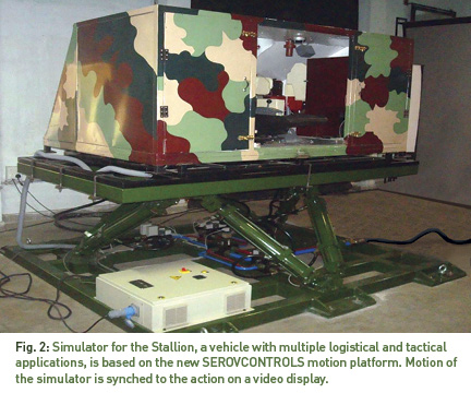
SERVOCONTROLS recently upgraded the motion platform of a driving simulator in order to solve a performance problem that the simulator was exhibiting. The simulator is used by a customer of rugged commercial and military vehicles manufactured by Tata and Leyland for driver training (Fig. 2). The previous control system used independent single-axis analog control cards, one to drive each of the six hydraulic actuators that move the platform with the gains set by adjusting potentiometers on the cards. In addition to having problems adjusting the axis gains correctly, the host computer, a Windows-based Industrial PC that provided analog position targets to the cards, wasn’t able to perform mathematical calculations quickly enough in order to keep the motion of the various axes synchronized with one another and also synchronized with the moving image on the simulator screen.
SERVOCONTROLS’ customer also tried using a PLC to control the motion axes but had similar synchronization problems. They decided that they needed a motion platform with a controller that has built-in support for controlling and synchronizing multiple motion axes and tuning for optimum performance. The customer came to SERVOCONTROLS for help.
The Solution: A Multi-Axis Motion Controller
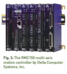
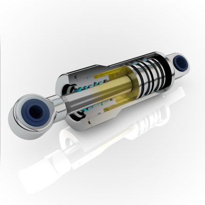
After reviewing the customer’s needs, SERVOCONTROLS recommended a motion platform design based on the RMC150 eight-axis electro-hydraulic motion controller manufactured by Delta Computer Systems, Inc., Battle Ground, Wash. (Fig. 3). “The Delta controller solves our greatest problem, which was synchronizing the axes,” said Deepak Dhadoti, managing director of SERVOCONTROLS.
 The new system uses the motion controller to perform the calculations, eliminating the delays that the old control system experienced. “The RMC150 incorporates an internal motion target generator,” said Dhadoti. “Every control loop, the target generator issues the appropriate control signal for each of the six proportional valves controlling the cylinders.” To receive position feedback indicating the current orientation of the platform, the motion controller connects directly to a linear magnetostrictive displacement transducer (LMDT) mounted in each cylinder.
To ensure that the motion of the axes is always synchronized, SERVOCONTROLS Engineer Vijay Prabhu used the built-in synchronization capability of the motion controller, specifically the “Ratioed Motion” functions performed by the RMC controller’s Synch Move Absolute and Synch Move Relative commands. In this type of synchronization, all six axes start and stop moving simultaneously, and at any point during the move, each axis has completed the same percentage distance (or ratio) of its move. The axes do not need to start or stop at the same positions. “Because the synchronization function is built into the controller, it is much easier to implement multi-axis control strategies with the RMC than it would have been using a PLC,” said Vijay Prabhu, manager of SERVOCONTROLS’ Electronics Division. To start a synchronized move, the programmer issues the appropriate Sync Move command simultaneously to each axis.
The math involved in order to calculate the ratios for the Synch Move commands is done by a user program running on the RMC controller. User programs are composed of a series of instructions that are executed by the controller once every control loop time and which can produce computed values to be deposited in the registers of the controller for reference by the control loop.
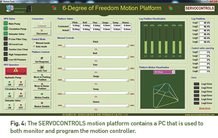
The Graphical User Interface (GUI) software running on the PC is interfaced to the RMC150 motion controller via Ethernet using Delta’s RMCLink software package. Fig. 4 shows one of the graphical user interface (GUI) screens that SERVOCONTROLS developed for the system. The GUI software controls the hydraulic power unit, as well as safety interlocks. The GUI software has a “file play” option where the pre-defined excursion data is stored in Excel/text format and can be read and fed to the RMC motion controller for execution.
After establishing the basic functionality of the motion platform, the SERVOCONTROLS engineers used programs from Delta Computer Systems’ RMCTools software package to tune and optimize how the system responds to inputs from the PC. One of these tools, the Plot Manager, allows the system designer to visually compare the actual operation of the system with the target motion profile specified by the motion program. The gain parameters of the control-loop equations are then adjusted until the actual and target values match. “Software tuning is much more reliable and easy to do than the old method of adjusting variable resistor components on an analog circuit board,” said Prabhu.
Now, the new motion platform generates smooth motion in synch with the projected video frame, simulating realistic driving feel with all dynamic characteristics. “In Simulation-related applications, providing a realistic operating experience is critical to achieving the main goals of the design,” said Prabhu. “Our customer’s former design based on analog technology failed to do that satisfactorily, but in our new motion platform, the math and synchronization features of RMC150 helped us achieve all of our design goals.”
By Rick Meyerhoefer, Delta Computer Systems Inc. For more information, visit www.deltamotion.com.
Share this information.
Related Posts
The International Construction and Utility Equipment Exposition (ICUEE)
Ensuring Proper Maintenance and Repair in Projects Involving an Elevated Height

How Fluid Power Helps Control Invisible Contaminants

Hydraulics are Fun!
Family Friction: Lubrication Management Grows Up
Ergonomic Lifting Made Easier with Vacuum Technology
Sponsor

Sponsors