Monitoring Hydraulic Pump Case Drain: Yes or No
By Steve Thorpe, Distribution Sales Manager, Webtec.
When the lifetimes of machine components are well-established and can be predicted reasonably accurately, then a preventive maintenance philosophy is a good one to adopt, and almost certainly better than relying on a breakdown maintenance approach. Preventive maintenance involves predicting the life or performance degradation of a component and scheduling its service or replacement at some time before the end of its useful life. Some components however operate with a large number of variables which can affect their rate of performance loss and a hydraulic pump is one such component. For example, the useful life of a pump can be affected by such factors as:
- The correct choice of pump for the application
- How the pump has been stored prior to use
- How the pump has been installed into the system
- The operating pressure and duty cycle of the application
- The pump drive speed
- The type and condition of the system fluid (temperature, cleanliness, etc.)
- The pump inlet conditions
- The correct setting and operation of the pump controls, where applicable
- The pump drain line layout
With so many operating variables, estimating the time when servicing or replacement of a pump is necessary will never be a simple exercise. Under-estimating pump life may result in a perfectly serviceable component, with many hours of useful life remaining, being replaced unnecessarily. Over estimating its life on the other hand could result in a catastrophic failure occurring before its scheduled replacement, with all the consequential cost and disruption that this is likely to cause. In such situations, therefore, a predictive maintenance procedure may be more appropriate where key characteristics of the pump’s performance are monitored either periodically, or preferably, continuously.
The next question to answer is therefore what are the key characteristics of a pump’s operation that will indicate its performance level? To answer this question, it’s first of all necessary to define the common failure modes of a typical pump. Consider therefore a variable displacement axial piston pump, a type that is very common on larger mobile machines and many industrial applications due to its good efficiency, high-pressure capability, and through-drive facility. Such pumps consist of usually 9 pistons fitted into bores in a rotating cylinder barrel. As the cylinder barrel rotates, an angled swash plate causes the pistons to reciprocate within their bores, with the stroke of the pistons being determined by the angle of the swash plate. Shoes or slippers on the end of each piston are held against the swash plate using a retaining plate and the flexible joint between the shoe and piston is achieved normally by swaging the shoe over the spherical end of the piston. In some designs, however, the piston mates with a spherical extension of the shoe. Inlet and outlet fluid passes via a valve plate on the rear of the pump to the pistons at the appropriate part of their cycle. A control piston positions the swash plate at any angle between maximum and zero in order to vary the pump displacement and in response to the action of one or more control valves mounted on the pump. In some designs, the adjustment piston lies on the same axis as the pump shaft, and in others at right angles to the shaft.
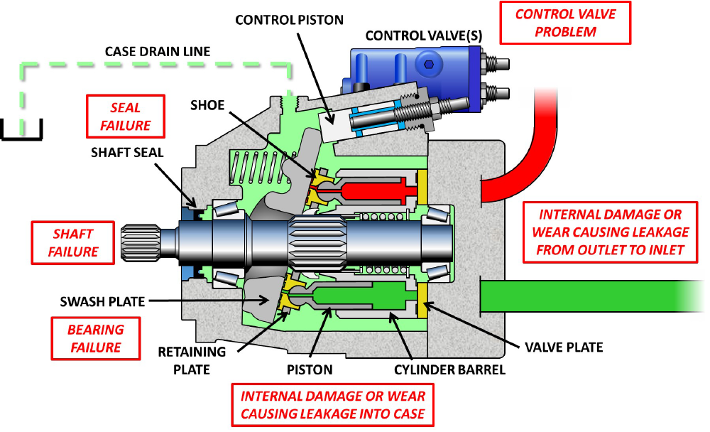
Figure 1 – Common failure modes of a variable displacement axial piston pump
Considering now the most common causes of pump failure, like all rotating devices, wear or damage to bearings will inevitably be high up on the list. There may be several reasons why pump shaft bearings fail but problems with the hydraulic fluid and excessive loading are the two most likely reasons. The wrong type or condition of the fluid together with contamination and temperature problems could all cause premature bearing failure as would excessive loading caused by shaft misalignment or over-pressurization. But of course, all bearings will have a finite life even when working within their rated conditions of service.
As mentioned, the swash plate of a variable displacement axial piston pump is designed to tilt to vary the pump’s displacement and is therefore mounted in a yoke which is supported on either side by either needle roller bearings or, more commonly, saddle-type bearings. Saddle bearings are often pressure lubricated but are still susceptible to failure by contaminated fluid.
Failures of the drive shaft are less common and are usually caused by bending, due to poor installation alignment, or from a severe over-pressurization of the pump resulting in a torsional failure. Torsion failures may of course also be a result of a catastrophic internal failure of the pump.
A leaking shaft seal may be a sign of either a worn seal or a high pump case pressure. Seals need to be lubricated to avoid excessive heat build-up and wear, so starting up a pump without pre-filling the case with fluid can cause premature seal failure. If a pump is started ‘dry’, i.e. with no fluid in the pump case, it can take a significant amount of time for internal leakage to fill up the case and provide the necessary lubrication for the shaft seal and other components, particularly if the pump output is unloaded during this time. Excessive temperature, contamination, and high continuous or peak case pressure are also factors that can result in leakage from the shaft seal.
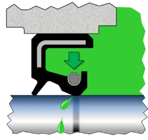
Figure 2. – A high case pressure can cause increased wear on the shaft seal leading to leakage from the seal.
Variable displacement pumps are controlled through pilot valves acting via a control piston or pistons, which change the angle of the swash plate to vary the pump displacement. Control valves may range from a simple pressure limiting compensator to a servo-controlled displacement mechanism and possibly combined with such features as load sensing and power limiting etc. Such control valves may always be susceptible to contamination jamming spools or blocking orifices and must also be set up and adjusted correctly both at start-up and throughout the pump’s operational life. A very common cause of excessive fluid temperature for example is when a pressure limiting compensator is adjusted to a pressure higher than the relief valve on the pump outlet. Excess pump flow then passes across the relief valve at full pressure instead of reducing the pump flow.
Like most hydraulic components, the biggest enemy of pumps is contamination. Normal or abnormal wear of a pump’s internal components will inevitably detract from the pump’s output flow. Wear or damage to the port plate or cylinder barrel face may tend to create leakage both directly from the high-pressure outlet port to the low-pressure inlet port or into the case of the pump. Leakage both from the piston/bore clearance and from the piston/shoe assembly will however always collect in the pump case from where it is directed back to the reservoir via the case drain line. It has long been assumed therefore that monitoring a pump’s case drain flow provides a very good indication of the wear state of the pump thus enabling an estimate to be made of the remaining useful life of the pump. While this is often a reasonable assumption to make, several factors need to be considered if this approach is adopted along with some pitfalls to be avoided.
Firstly, as mentioned, not all internal leakage will be collected in the pump case and therefore will not be apparent as excessive flow in the case drain line. Scoring of the valve plate or cylinder barrel end face caused by contamination will often allow high-pressure fluid to pass straight back into the inlet port thus reducing the net output flow. Some pump designs incorporate a case-to-inlet port check valve, designed to limit the case pressure, so again excessive internal leakage may not show up as increased flow in the case drain line. Also, tandem pumps sometimes share a common case drain line, (by removing the shaft seal from the rear pump), thus making it impossible to determine which pump is losing efficiency or if the efficiency loss is due to both pumps.
Secondly, any component mounted in the case drain line is likely to add restriction to the drain flow and thus increase the pressure within the pump case, and as already mentioned, shaft seal performance can be reduced by a high case pressure. But apart from its effect on the pump shaft seal, a high case pressure can also cause a more serious issue with the pump. For the pistons on the suction side of the pump, a high case pressure tends to push each piston back into its bore acting against the very low pressure inside the piston bore. The purpose of the retaining plate is to counteract this out-of-balance pressure force and hold the piston shoes in contact with the swash plate on the suction side of the pumping cycle. Where the pump design uses a spring-loaded retaining plate, an excessively high case pressure can overcome the spring force and allow the piston shoes to lift off the swash plate thus causing them to tilt and allowing the metal-to-metal contact between shoe and swash plate. Semi-circular marks on the swash plate surface together with indentations on the edges of the retaining plate holes are characteristic signs of such shoe lift occurring.
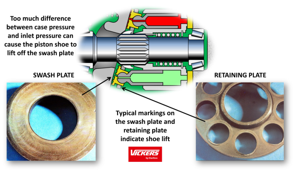
Figure 3. – Swashplate marking and retaining plate indentations indicate shoe lift (Photo credit Danfoss)
When the pump incorporates a fixed clearance retaining plate then an excessive out-of-balance pressure force acting on the piston can separate the shoe from the spherical end of the piston, which inevitably results in an immediate total failure of the pump.
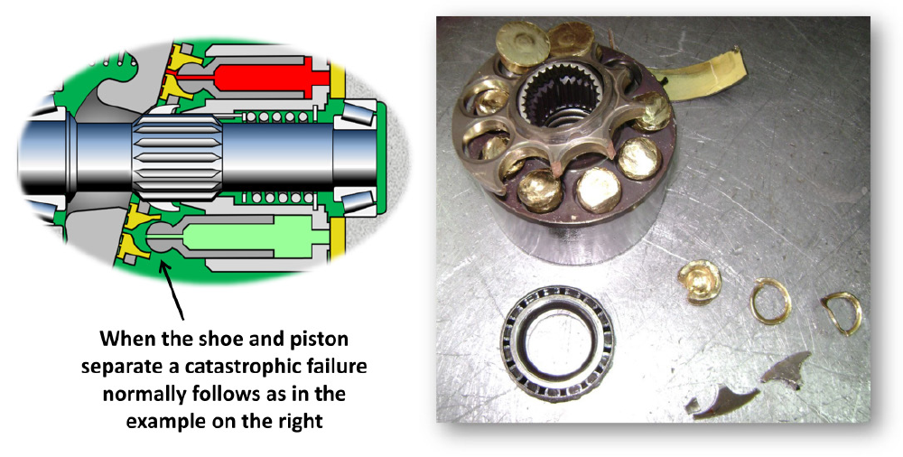
Figure 4. – Piston, shoe, and retaining plate failure caused by high case pressure
(Photo credit www.insanehydraulics.com)
To maintain the out-of-balance pressure force acting on the pistons within an acceptable level, most pump manufacturers specify a maximum pressure difference between the case pressure and the inlet port pressure, which is typically 50 kPa (7.5 psi). It must be remembered however that at maximum stroke angle, the suction pistons are traveling at a high velocity both linearly within their bores and rotationally with the cylinder barrel. So, by the time the fluid has squeezed through the narrow openings of the valve plate and cylinder barrel, accelerated up to the linear and rotational speed of the piston, and then filled the piston bore, its pressure will be close to absolute zero and certainly well below the pressure that can be measured at the inlet port. But even when subjected to such a pressure imbalance, the resultant force would not seem to be great enough to separate the piston and shoe without some other factor having an effect.
In many cases, the other factor may be the result of a single swash plate control piston causing a transient pressure peak in the pump case. As the pump moves from a high flow to a lower flow condition, involving a reduced swashplate angle, the control piston extends rapidly and displaces its volume of fluid from the pump case. This can create a momentary high flow rate in the case drain line and a consequent high peak pressure in the case if the drain line is restricted in any way. Data on such peak drain line flows is rather scarce but Parker quotes a figure of up to 120 L/min (31.7 gpm) for a 140 cm³/r (8.5 in³) pump which is almost half the full pump flow at 1800 rpm drive speed. So, where the drain connection, and any components mounted in it, have been sized for an expected flow rate of 10 to 15 L/min (2.6 to 4.0 gpm), (4 to 6% of the theoretical pump output flow), a momentary flow rate of 120 L/min (31.7 gpm) is likely to create a high peak pressure in the pump case. At 1800 rpm each piston and shoe assembly is squeezed and stretched 30 times a second so if the high case pressure is creating a stretching force greater than it should be, the swaged connection between the spherical end of the piston and the shoe will eventually loosen and subsequently fail prematurely. Of course, when the control piston retracts to bring the pump back onto stroke a reverse flow can occur in the drain line.
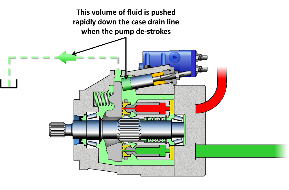
Figure 5. – Control piston displacement creates a peak drain line flow
For these reasons, the drain line of variable piston pumps should be as large and unrestricted as possible and even the relatively low restriction created by a permanently installed turbine-type flow meter may be enough to reduce the working life of a pump. Connecting a flow meter to the drain line on an occasional (but regular) basis is therefore preferable to a permanently installed unit, but care must be taken to ensure that flow meter readings are taken under the same pump operating conditions (displacement, speed, pressure, temperature, etc), which may not always be easy to do unless carried out using a defined test routine, and most likely with the machine off-line.
In practice, therefore, a permanently installed flow monitor in the pump outlet may be the best way to continuously record the pump flow performance provided that the operating conditions that affect pump flow rate can also be monitored. For a variable displacement pump, these would include:
- The pump drive speed
- The swash plate angle (pump displacement)
- The output fluid pressure
- The fluid temperature (viscosity)
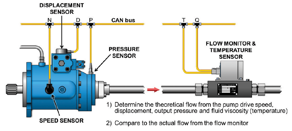
Figure 6. – Monitoring pump flow performance with the Webtec CTA Series Flow Monitor
On mobile machinery, the pump drive speed can be derived from the engine speed, which is normally monitored as a matter of course. Swash plate angle sensors are a common option on many variable pumps and pressure sensors are also standard fitment on many machines. By using an output flow monitor that also senses fluid temperature, the final factor affecting the pump flow rate can also be accounted for.
Webtec’s CTA Series Flow Monitors are therefore ideally suited to form part of a predictive maintenance system, where they can continuously monitor pump output flow performance at pressures up to 42 MPa (6,090 psi) and flow rates up to 300 L/min (79.3 gpm) while simultaneously sensing fluid temperature. The principle of operation is a well-proven design that uses a turbine wheel mounted in the flow stream and a sensor that senses the passing of each turbine blade. As flow passes through the flow monitor, the turbine blade spins around at a speed proportional to the flow rate. The onboard electronics then convert the sensor pulses into a flow rate signal which can be transmitted via an SAE J1939 CANbus signal to the vehicle’s main supervisory control system or via a telematic link to a centralized monitoring and diagnostic station.
Despite the minimal restriction created by such flow monitors, mounting the units in the outlet port of variable displacement axial piston pumps is the preferred arrangement rather than in the case drain line. Fitment into the drain lines of fixed displacement pumps and motors is much less problematic however since high transient drain line flows are less likely to occur. In combination with a suitable vibration sensor to monitor the bearing condition, a full and continuous health check can then be maintained on the pump, and appropriate action taken to avoid the disruption and cost of unexpected breakdowns.
So before using case drain flow monitoring consider the following:
- Not all internal leakage from pumps and motors is evident as case drain flow
- Components mounted in case drain lines should not adversely increase the case pressure
- Check manufacturer’s specifications for maximum case pressures and case-to-inlet differential pressures when appropriate
- Transient flows in variable displacement pump drain lines can be very high
- Case drain flow rates will vary considerably with pump or motor operating pressure
- Control orifices of variable pumps often increase drain line flow at zero displacement
Share this information.
Related Posts

Utilizing Pressure Sensors to Enhance Pneumatic Pressure Control in Robotics
Fan Drives in Mobile Hydraulic Applications

2014 Manufacturers Listing and Matrix
Endress+Hauser Launches Temperature Transmitter with Bluetooth

Hydraulic Oil vs. Seal Lip Material
Festo Controls Help Glue Electronic Components
Sponsor

Sponsors