Motion Control of a Unidirectional and Bidirectional Motor
This series of articles covers the basic safety and energy-saving requirements of a hydraulic system. This third installment presents ideas for motion control of a single hydraulic actuator against resistive and running load.
 Unidirectional Motor
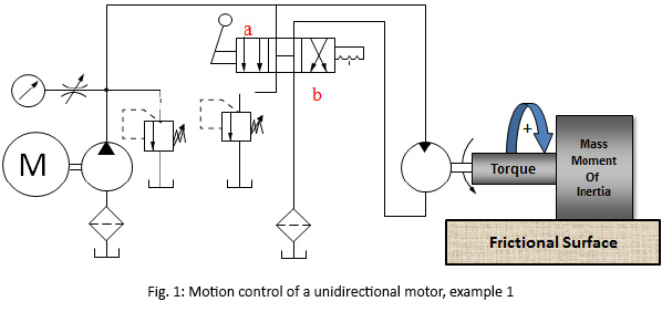
 Assuming a unidirectional hydraulic motor experiences an external resistive torque, similar to a single-acting cylinder, it can be driven by a 2-way or 3-way valve. Fig. 1 shows one circuit, in which a 4-way valve is used to control the motion of the motor. In such a circuit, an electric motor drives a fixed-displacement pump. The pump outlet is connected to an open center, 4-way, 3-position directional-control valve. One main pressure-relief valve is used to limit the maximum pressure in the system; one other pressure-relief valve is used to bring the motor to a controlled stop.
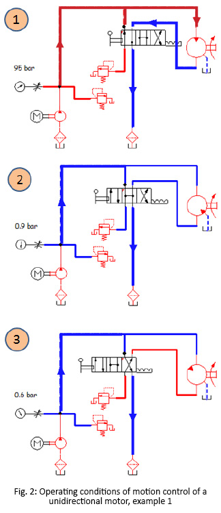
Fig. 2 shows the operating conditions of the circuit shown in Fig. 1. Part 1 of the figure shows that the motor is driven by shifting the directional valve to position “a.” Part 2 of the figure shows that, by putting the valve in its center position, the pump is unloaded and the motor shaft will be free to rotate. Part 3 of the figure shows that, by shifting the directional-control valve to position “b”, the pump is unloaded and the motor is forced to stop against the second pressure-relief valve.
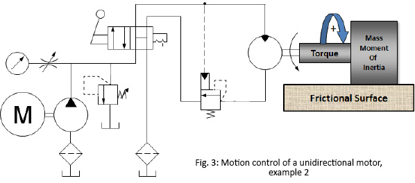
Fig. 3 shows another circuit to control the motion of a unidirectional hydraulic motor. In such a circuit, a motor brake valve is used to top the motor in a short time. The pump outlet is connected to an open-center, 4-way, 2-position directional-control valve.
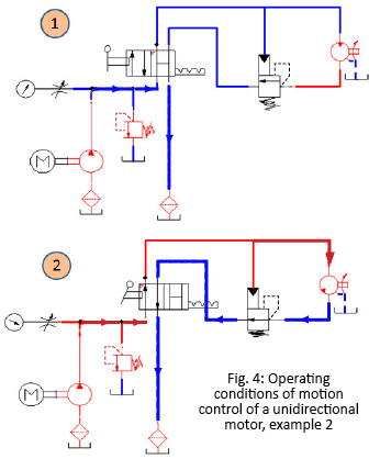
Fig. 4 shows the operating conditions of the circuit shown in Fig. 3. Part 1 of the figure shows that, by putting the valve in its initial position, the motor is stopped in one direction by the motor brake valve. Part 2 of the figure shows that, by shifting the valve, the pump is unloaded and the motor is forced to stop against the motor brake valve.
Bidirectional Motor
Like driving a double-acting cylinder, a 4-way, 3-position directional control valve (DCV) is used. The specific type of center condition recommended is dependent on the dynamics of the system as described in the cases below.
 Case 1: The motor is slowly spinning and does not drive a large rotational inertial load.
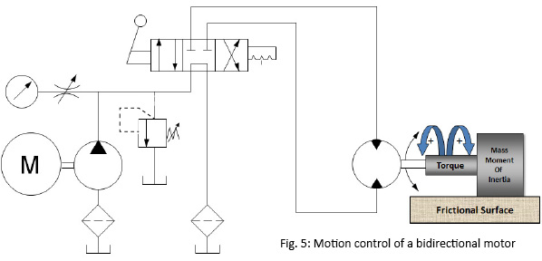
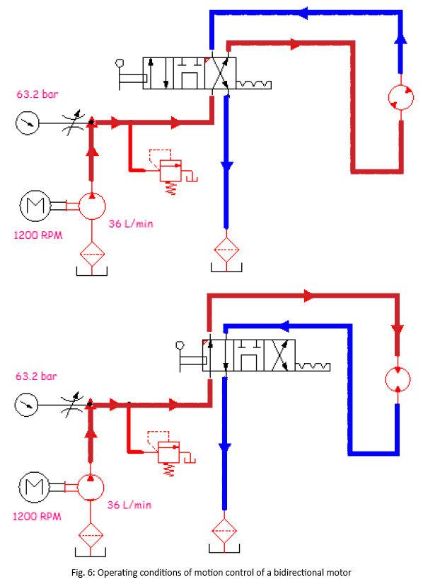
- Tandem-Center DCV is recommended with a fixed pump that is unloaded through the center position of the valve, as shown in Fig. 5. Fig. 6 shows the operating conditions for the circuit shown in Fig. 5.
- Closed-Center DCV is used with a pressure-compensated pump that de-strokes itself at the center position of the valve so that it saves the energy.
Case 2: The motor is spinning fast or driving a large rotational load, and there is no requirement to stop the motor in a short time in order to avoid generating pressure spikes in the system.
- Open-Center DCV s recommended with a fixed pump that is unloaded through the center position of the valve. The motor will take some time to stop. It is to be noted that, so far, the motor is assumed to spin against resistive load in both directions.
- Float-Center DCV is used with a pressure-compensated pump.
Case 3: The motor is spinning fast or driving a large rotational load, and there is a requirement to stop the motor in short time.
- Open-center DCV is used with a double motor brake.





we have problem of hydromotor driven 300 ton carriage.problem is -itis not stoping when we want to stop at position. this happen atboth forward and reverse direction.