Self-Closing Valves
In most vacuum-handling applications, the end-of-arm tool (EOAT) is designed specifically for the product being handled by the automated material-handling device, such as a robot or pick-and-place machine. This allows for a very simple selection and installation of the necessary vacuum components, such as cups, vacuum-generation device (venturi or pump), and associated equipment, such as filtration and vacuum sensors.
Fig. 1 shows a typical EOAT designed to handle an 8″ x 12″ (200 mm x 300 mm) cardboard box. All six rows of vacuum cups are sealed against the cardboard box (indicated in yellow) and share, via the common vacuum manifold, the same centralized vacuum source. The volume between the vacuum-generation device and the cup sealing face will be equalized at a common vacuum level when vacuum is applied to the cups via the manifold.

However, if different-size loads are being handled, which means in some cases the product does NOT cover all of the vacuum cups as shown in Fig. 2, then leakage will occur (cup rows 5 & 6 in this example) in this common vacuum source system. Therefore, the complete vacuum system level will be decreased to such a point as to make the EOAT ineffective in handling the smaller footprint load. Of course this can be overcome by a vacuum pump with excessive flow capacity that can compensate for leakage, but that is energy and cost prohibitive, particularly on very large vacuum heads.

To overcome this, many machine builders implement individual vacuum generation for each vacuum cup, as shown in Fig. 3. This is very effective when handling different-size loads, but the disadvantages are numerous, including high total energy consumption for operating individual vacuum generators (venturi), increased filtration maintenance for each venturi, increased interconnecting pipework for compressed air supply lines, a more complicated and certainly untidy installation, and typically an increased overall machine noise level.

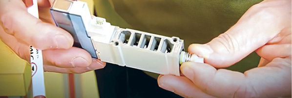
An alternative method for picking up multiple-size loads is to use a self-closing valve, which “senses” excessive vacuum flow (leakage) and then automatically closes to isolate a cup from the remainder of the common system if that cup does not seal against a load. Fig. 4 shows a valve of this nature in unassembled component form and assembled.

The body (a) houses three components: spring (b), sealing ball (c), and adjustment screw (d). A common misunderstanding of this type of valve is that users refer to it as a “check valve.” This is not a check valve. A check valve or non-return valve allows flow in only one direction. This self-closing valve can flow in both directions to allow release of the part being handled when the vacuum power is turned off. The cutaway shown in Fig. 5 shows how the valve works. The state on the left is when the vacuum is turned off or when a cup has sealed properly against the load to be lifted. The ball is pushed down against the adjustment screw (d) (not shown in the cutaway), and air is allowed to pass by the ball. If the cup does not seal on the load and is leaking, this excessive air flow “pushes” the sealing ball against a conical seat, isolating that single cup from the rest of the system. This condition is shown on the right in Fig. 5. This allows the remaining cups in contact with the load to gain full system vacuum.

The assembly in Fig. 6 shows these self-closing valves installed in a common vacuum source lifting head that uses 12 rows of vacuum cups. Rows 7-12 are NOT sealing on the load, and therefore, the associated valve on each cup is CLOSED. The valves attached to the cups sealed on the load (rows 1 through 6) remain open.

This particular type of self-closing valve is also adjustable to allow more or less flow to close the valve. This is a useful feature if the load being handled is porous or indeed the cups that the self-closing valve is attached to are very large. The actual air volume inside a large cup could actually close a valve of the non-adjustment type, even if it is sealed against the load. The adjustment screw (d) can be screwed OUTWARDS to allow for excessive air flow and screwed INWARDS when used on very small vacuum cups.
As in most vacuum-handling applications, there are many methods used to obtain the same end result. However, the use of self-closing valves offers the machine builder a very simple and effective multiple-size load-handling solution.
This article is intended as a general guide and as with any industrial application involving machinery choice, independent professional advice should be sought to ensure correct selection and installation.
Daniel Pascoe is General Manager of Vacuforce Inc, manufacturer and distributor of vacuum components and systems for industry in North America. Daniel can be reached via the Vacuforce website at www.vacuforce.com, or directly at dpascoe@vacuforce.com. Find Vacuforce on Facebook and keep up-to-date on Twitter.
Share this information.
Related Posts


Sponsor

Sponsors