Servo Valves Key to Aircraft Carrier Application
By Matthew McCall, Regional Sales Manager, Moog Inc.

An F/A-18F Super Hornet (Photo courtesy of U.S. Navy. Photo by Mass Communication Specialist 2nd Class Ryan Seelbach/Released)
Servo and proportional valves are most commonly flow-control, spool-type valves that meter fluid from a high-pressure source—typically a pump or accumulator system—to a rotary or linear actuator of some sort. From the actuator, the fluid then passes back through the valve, returning to the low-pressure tank or reservoir, making it a “meter-in/meter-out” valve. They control position, velocity, or pressure and/or force through a closed-loop electronic control system. These valves are extremely responsive dynamically, reaching commanded setpoints in milliseconds of receiving a command (generally ~1ms to <100ms).
What makes a servo valve different than a proportional valve? A servo utilizes a spool-in-bushing design, allowing for extremely precise fluid metering, with minimal leakage due to a controlled, tight diametric fit between the spool and its matched bushing, measured in millionths of an inch. With proportional valves, the spool fits neatly into the body itself, allowing for higher flows but with less precision and higher leakage. Fitment between the body and spool is typically measured in the ten-thousandths of an inch range. Both valve types use various methods to drive and position the spool, including mechanical feedback systems using no electronics and electrical feedback systems using an LVDT to measure the spool position. The three main spool driving systems are the nozzle/flapper hydraulic pilot design, jet-pipe hydraulic pilot design, and direct drive design, which does not use a hydraulic pilot but rather drives the spool with a mechanical linkage affixed to a linear or rotary motor or solenoid. Each design has its place in the military world: servo for extreme accuracy and precision and proportional for higher flow applications requiring less precision.
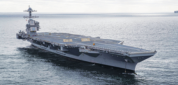
The USS Gerald R. Ford (Photo courtesy of U.S. Navy. Photo by Mass Communication Specialist 3rd Class Connor Loessin/Released)
Where might you find a servo or proportional valve in a military or defense application? Look for jobs requiring the highest levels of response, reliability, precision, and accuracy. Controlling actuation systems on supersonic fighter jets and launch vehicles? Check. Stabilizing gun turrets or positioning RADAR arrays and communications antennas? Check. Testing the next generation of advanced materials in a classified lab? Check. Thrust vector control on rockets and fin control on missile systems? Check. Catching an aircraft on the deck of the USS Gerald R. Ford? Check.
The USS Gerald R. Ford (CVN-78) is the latest and greatest aircraft carrier in the U.S. Navy’s fleet. Commissioned in July 2017, it is the largest and most advanced aircraft carrier in the world at roughly 1,100 feet in length, nearly 260 feet in beam, 25 stories tall from keel to tower, and displacing roughly 100,000 tons. The twin nuclear reactors power the ship to over 35 knots, carrying up to 90 aircraft, with a crew of around 6,000 sailors. It is a well-equipped, well-armed, floating city.
Some of the major technological advancements over the previous Nimitz-class carriers include an electromagnetic aircraft launch system and an advanced arresting gear system (AAG), which relies heavily on high-performance digital servo valves to precisely and accurately catch more than a half-dozen models of aircraft, each with a unique arresting profile.
The AAG is a unique example of a servo valve in a military application. There are two servo valves per arresting cable and three cables per carrier. The cables sit just above the deck of the carrier, suspended by leaf springs, and engage a tail-hook on the aircraft as it lands. This system is capable of stopping planes moving at roughly 150 mph in less than 350 feet and in less than two seconds. So how do these cables absorb all that kinetic energy? Each cable is connected to a series of pulleys, water twisters, cushioning cylinders, and sheeves that are connected to a hydraulic brake. A servo valve modulates the hydraulic pressure to the brake, which works in conjunction with the water twisters to control the tension of the arresting cables both while static and when arresting an aircraft. The AAG system was designed to allow the Ford-class carriers to perform up to 270 sorties per day in extreme conditions.
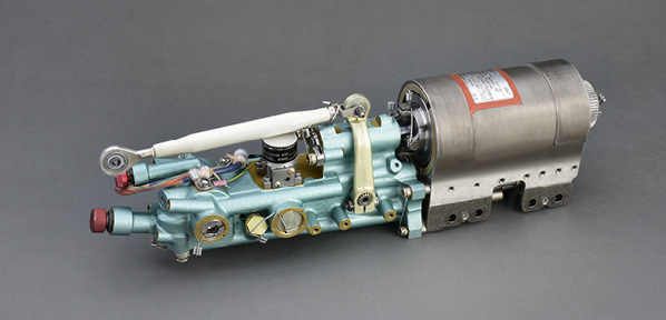
F-15A-E rudder servo actuator and valve assembly (Photo courtesy of Moog Inc.)
The pressure on each brake is critical throughout the entire arrestment. Each aircraft requires a precise cable tension, which changes continuously throughout that two-second catchment to ensure the aircraft and its crew or payload are caught safely. Too much tension on the cable risks damaging the plane and injuring the crew; it could also snap the arresting cable, risking injury to those on the flight deck and failing to stop the plane. Too little pressure on the cable causes the plane to overshoot the landing and engage the end-stops of the cable, risking damage to the plane, the cable, and those on the flight deck. Any pressure variance between the two brakes during an arrestment could pull the cable to one side, causing the landing aircraft to veer off course, potentially off the flight deck, or into the control tower. There is no margin for error in this mission-critical application. For this reason, the precision, accuracy, and responsiveness of a servo valve is a necessity.
To minimize leakage and be as efficient as possible, designers chose a direct drive, axis control style servo valve. The direct drive design features a linear force motor in place of a hydraulic pilot, eliminating the typical pilot-stage leakage associated with multistage valves but maintaining the responsiveness required for critical pressure control applications. Each brake has its own hydraulic power unit, which cycles intermittently to charge an accumulator that provides pressure to the servo valve and braking system, making valve leakage a major concern in the systems design.
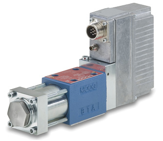
Moog D638 series valve
(Photo courtesy of Moog Inc.)
Previous Nimitz-class carriers’ Mark 7 arresting gear also used a servo valve for cable tensioning. But the Ford class is the first to use a servo valve with an onboard pressure transducer and onboard electronics, and it is one of the first applications of a digital axis control valve in any military application. The onboard pressure transducer and electronics allow the valve to perform the PID loop closure for pressure control within the valve, eliminating the need for a separate controller and feedback system. This greatly reduced the system complexity, componentry, and increased its reliability. The digital control functionality allowed the system designers to continuously tune the valve for things like loop and system gains, dead band compensation, signal filtering, command signal modifications, I/O and feedback modifications, and failsafe changes, many of which proved critical during development of the new AAG system. Additionally, the digital communication and software eases troubleshooting and commissioning, and it can offer insight into the health and performance of the valve both during operation and while disabled.
Though the valves can communicate over several fieldbus options to relay command, feedback, and parameter information, the AAG application uses the analog control functions and no network connection to limit security risks that can be associated with network-enabled controls. The valves are programmed for the application before being installed on the ship, and if a need arises to troubleshoot or diagnose a system issue while the valve is installed, a laptop can be connected to the valve via a service connector, and all parameters can be viewed or adjusted as required.
While catching aircraft on a 100,000-ton aircraft carrier may not seem relevant to a typical commercial or industrial fluid power application, the basic pressure control or precision metering control capabilities of servo or proportional valves are widely used in civilian industry. The benefits and features that make these types of valves ideal for military applications can also improve productivity and quality in civilian applications. They can also reduce operating and maintenance costs with advanced diagnostic and troubleshooting capabilities. For an application that requires the highest levels of precision motion control, high reliability, or reduced operating costs, the needed solution might be a servo or proportional valve.
*NAVAIR Public Release 2020-398. Distribution Statement A – “Approved for public release; distribution is unlimited.”
Share this information.
Related Posts

Flow Means “Go”…Well, Not Exactly.

Technical Cleanliness: Examining the Use of ISO 18413 for Pressure Rinsing

What’s Your Standby Efficiency?
Newly Developed: Pneumatic Solution Ensures Model Polyethylene Terephthalate (PET) Bottles

Case Study: Building Seaworthy Hydraulic Cylinders

Hydraulic Oil vs. Seal Lip Material
Sponsor

Sponsors