Technical Cleanliness: Examining the Use of ISO 18413 for Pressure Rinsing
By Brian Schreiber, CFPS, HYDAC Technology Corporation
1. Introduction
In the Fluid Power Industry, hydraulic fluid cleanliness is most commonly associated with ISO 4406. This widely used and accepted standard provides guidelines for characterizing and establishing a particular fluid’s cleanliness level, based on particle counts of the contaminants within the fluid. But what about the cleanliness of the components that make up the hydraulic circuit (pumps, valves, accumulators, fittings, etc.); how is the cleanliness of fluid power assemblies and individual components determined? ISO 18413 is one standard that provides a controlled and validated way to establish the cleanliness of such components. Within this standard, there are four extraction methods detailed to test a variety of assemblies and components. Outlined below is one of these methods and the basic principles used to validate, qualify, and perform a correct extraction on a given part.
A commonly used extraction in ISO 18413 is the pressure-rinse technique. By means of a relatively low pressurized stream of solvent, controlled surface areas of a part are rinsed of contaminants. The extracted contaminant is then analyzed for concentrations such as mass, particle size and number of particles. The HYDAC CTU1000 Series Contamination Test Unit is one piece of equipment that can effectively validate and perform pressure rinse extractions. Its circuit allows for filtered solvent (1.9 mm2/s at 25 C) to be dispensed via one of two available spray guns in a controlled test chamber. The test chamber is under vacuum, and the contaminated solvent is directed to a filter membrane during the process. The solvent is then directed to a cleanup filter before returning to the storage reservoir.
2. Blank Value
In order to begin any extraction, a blank value of the test chamber being used must be obtained. A blank value is required to verify that the equipment is not contributing a significant amount of contaminant in the extraction. The HYDAC CTU extraction chamber is thoroughly rinsed and the blank value can be established for mass and/or particle size. The chamber is validated to ensure that the blank level is 10% of the presumed or required amount. For example, if the minimum amount of allowable containment is 7 mg on a given test part, the blank value must be 0.7 mg or lower. It is important to use the same parameters in the blank value as in the extraction. If the blank value is not successful on the first try, additional and thorough cleaning of the chamber must be performed, after which validation is again checked. Alternatively, the parts may be too clean for a blank to be obtained; therefore, the number of test parts must be increased.
3. Validation of Extraction
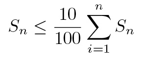
Once the blank value is obtained, qualification of the extraction parameters can begin. An extraction curve (or decay curve) is used to validate the selected parameters of the rinse on the part under test. With the HYDAC CTU, a selection of pressure (for example in the 100 to 400 kPa range) and volume of solvent (measured in l) is selected to rinse a given part. Using the spray guns, solvent is directed to the controlled areas of the part, making careful attempts to completely wash the surface. Controlled surfaces are those that come into contact with the system fluid (hydraulic system) during normal operation. Areas that are not in contact with the system fluid are not subject to these procedures. Once the part has completed the extraction process, the interior surfaces of the cabinet are rinsed, and all collection solvent is pulled through the filter membrane by vacuum. From this collected contaminant, the total cumulated mass of contaminant, or number of particles, is established. Continue to rinse the part (collecting contaminants separately between rinses) and divide the result of the last sample by the sum of all the measurements made. Validation is obtained once this value is 0.10 of sample Sn.
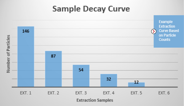
The results from an extraction can be graphed or presented in tabular form. The chart above is one example of an extraction curve. In this example, the part was subject to a pressure rinse of 200 kPa with 1.0 l of solvent. Upon the 5th extraction (S5) the validation was completed.
4. Testing and Reporting
Under the validated parameters, extraction of all parts is carried out and the collected contamination on the filter membrane can then be analyzed, referencing standards like ISO 4405 for gravimetric results and ISO 4407 for largest particle. This data is provided in an inspection report which includes the details of extraction equipment and parameters, the part under test, blank value, extraction curve and details on the position of the part under extraction with the spray gun and the part’s position during collection.
If you would like to get involved in fluid power standards development, please contact Denise Husenica, dhusenica@nfpa.com, for more information.
References
[1] ISO 18413:2015(E) Hydraulic Fluid Power-Cleanliness of components- Inspection document and principles related to contaminant extraction and analysis, and data reporting, Standard, International Organization for Standards, Geneva, CH.
Share this information.
Related Posts


Sponsor

Sponsors