Sizing an Air Motor

 Although electric motors are very commonly found in many varied applications, and hydraulic motors are well known for their high power density, air motors fill a unique niche in power and motion control applications. Air motors are relatively small and lightweight sources of smooth, vibration-less power. Air motors can be stopped and started almost instantly. They can provide variable torque and speed without complicated controls. They can operate in hot, corrosive, and wet environments without damage, and are unaffected by continuous stalling or overload. Therefore, there’s no heat buildup or electric sparks to damage the motor. Compared with hydraulic motors, air motors have a lower torque and power-to-weight ratio (power density). However, compressed air offers special advantages that make air motors quite desirable: it’s readily available, it’s relatively clean, and it can be directed to air motors with simple low-pressure piping. There are hundreds of uses for air motors.
The most common types of air motors are axial piston, radial piston, rotary vane, and gear/gerotor. As may be expected, each type has its distinct advantages and disadvantages. The application requirements determine which type of motor should be selected but they all share the same common sizing and selection criteria.
A unique characteristic of air motors is that their power output increases with increasing speed until it peaks at around 50% of free speed (maximum speed under no-load conditions).
At the peak point, torque capability begins to decrease as the speed increases. Power decreases to zero when torque is zero because all the inlet air power is used to force the volume of air required to maintain this speed through the motor.
Torque output for an air motor of given displacement is theoretically a function of the differential pressure across the motor. Therefore, regardless of speed, torque should be constant for a given operating pressure. However, as air flow increases through the motor to increase the speed, pressure losses in the inlet and outlet lines consume a greater portion of the supply and therefore the torque output decreases. In practice, torque reaches its greatest value shortly beyond zero speed and falls off rapidly until it reaches zero at free speed.
A motor should be selected based on the peak power point, when possible, to ensure that the motor is operating at its greatest efficiency. Air motors are usually sized by their horsepower at rated input air supply, usually in the range between 80 and 90 psig. Then this air consumption is used to size the valving and the compressor. The horsepower and speed of a given motor can be changed by throttling the inlet, so the common practice is to size the motor to provide the torque needed at 2/3 of line pressure. This point is approximately the peak power point of the motor performance curve. Full line pressure can then be used for start-up and overloads.
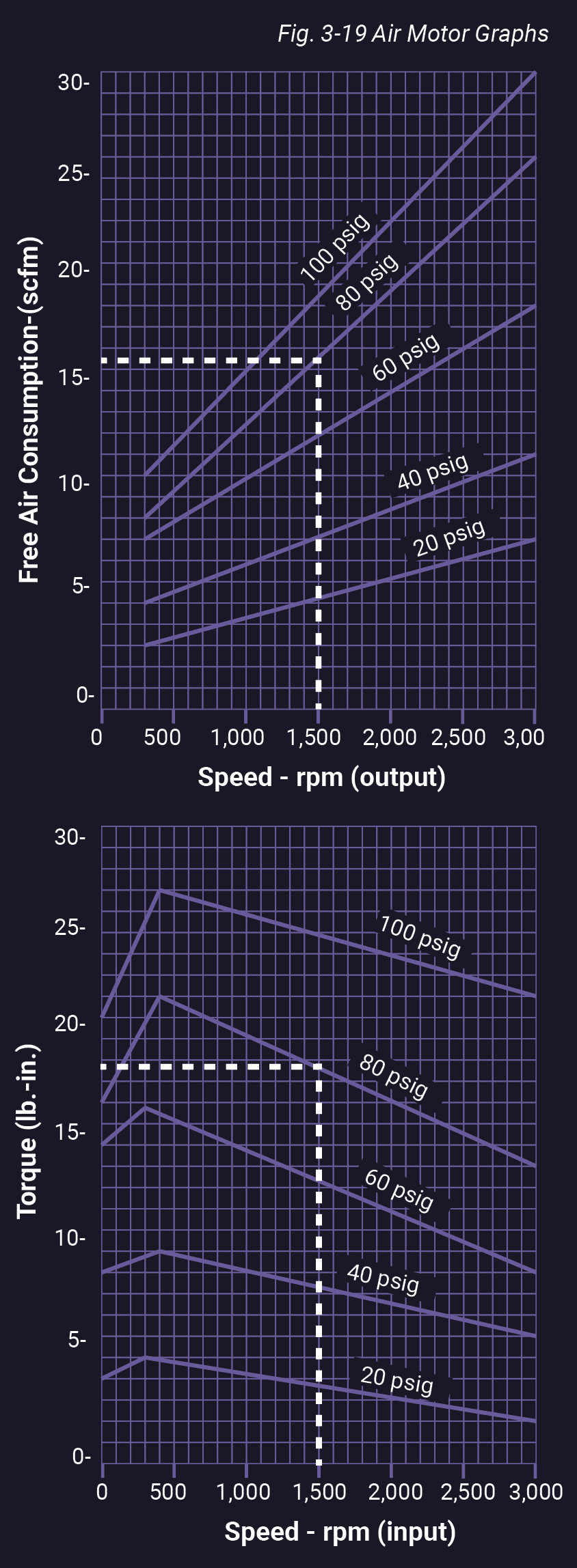
Each manufacturer supplies curves with the power output range given for several pressures. If for example, a 1 hp motor were required with a speed of 1,500 rpm, the motor would be selected that provided this power at 2/3 of the line pressure available. Fig. 3-19 (on the next page) shows two common graphs used to rate air motors. The left graph shows air consumption of a given displacement motor at different supply pressures and the graph on the right shows torque capability versus speed for that motor again at the supply pressures shown. Note that the pressures referenced are what the pressure should be at the motor inlet and not compressor output pressure.
The graphs in Fig. 3-19 are helpful to make calculations for motor torque and air consumption. If the rotation speed and the power required are known, then using Eq. 2.5 torque can be determined. Once that is known then the graph can be used to determine what supply pressure is required, along with what the required air consumption would be at that point.
Test Your Skills
1. A 1/4 hp air motor is selected to operate at 1,200 rpm. Using various calculations and the graphs in Fig. 3-19, what minimum air pressure listed would be required?
A. 30 psig.
B. 40 psig.
C. 50 psig.
D. 60 psig.
E. 70 psig.
2. If an air motor operates under load at 2,000 rpm and develops 17 lb-in. of torque, approximately how much air in scfm will it consume? Use Fig. 3-19 to derive an answer.
A. 10 scfm.
B. 15 scfm.
C. 20 scfm.
D. 25 scfm.
E. 30 scfm.

