Test Your Skills: Hydraulic Components in Circuits–Mobile Valves
Load-sensing valves are designed to be used with a load-sensing pump. The valves typically have spools with metering notches allowing proportional control of the affective orifice caused by the spool movement, both to the A and B ports. A shuttle valve usually allows the signal from the port with the higher pressure to be sensed by the pump control. Bernoulli taught us that there would be a discrete flow rate for a given pressure drop across an orifice. If the load-sensing compensator at the pump is set for a 17 bar (246 psi) differential, then any spool position will have a constant flow rate, regardless of variations in load pressure. This is particularly useful in mobile equipment when the valve is manually operated, and the only feedback is from the operator. However, if more than one function is being operated, the function with the greatest pressure-demand will be load-sensing. Other functions will no longer have a steady flow for a given spool position.
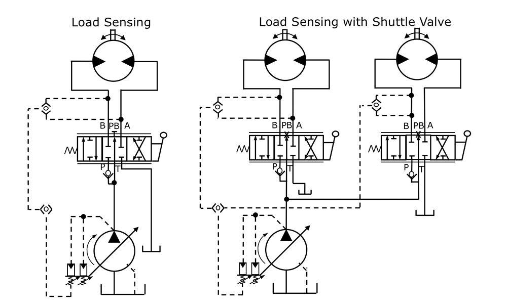
Figure 1: Load sense schematic.
Load-sensing valves with compensation. A load-sensing system that operates only one actuator at a time will supply the proper flow and pressure to that function because there is a consistent pressure drop across the control orifice. However, when there are multiple functions that need to be controlled at the same time, the function with the highest pressure requirement determines the core system pressure. Circuit sections that need lower pressure will receive an increase in flow due to this increase in core pressure. To overcome this problem, flow control compensators can be added to the circuit, usually within the main valve body of each valve section. There are two types of these compensator arrangements: precompensation, in which the additional valve element is placed in the fluid stream before it has passed by the control orifice (usually the main valve spool); and postcompensation, in which the additional valve element is placed in the fluid stream after it has passed by the control orifice. Both types of compensators sense core pressure and when required add restrictions to ensure a constant pressure drop across each control orifice regardless of load pressure differences.
In the first arrangement, the normally open precompensator valve element senses the load pressure, and if the pressure from the pump is higher than the compensator spring setting, nominally 17 bar (246 psi) above the load pressure, the compensator valve element restricts the flow and reduces the pressure across the control orifice to 17 bar (246 psi) above load pressure. The compensator is similar to a pressure reducing valve set at 17 bar (246 psi) with its spring chamber vented to the working port. The working port pressure is added to the spring setting of the valve. The result is a relatively consistent pressure drop related to the spring force and consequent flow rate for a given spool position, regardless of pump pressure or working port load pressure changes. This mitigates against the interaction of functions as long as there is enough pump flow to satisfy all activated work functions. The precompensator arrangement is best suited for accurate flow regulation circuits.
For example, in the precompensation circuit shown in figure 2a, pump flow maximum is 45 lpm (11.9 gpm). Note: The load-sense differential setting of the pump is 20 bar (290 psi). Function 1 maximum is 30 lpm (7.9 gpm), 100 bar (1,450 psi). Function 2 maximum is 25 lpm (6.6 gpm), 210 bar (3,045 psi).
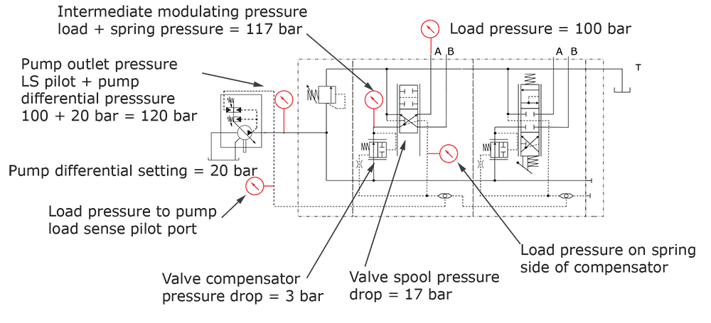
Figure 2a: Precompensation, one valve actuated.
Figure 2a shows the operation of one function. If function 1 is operating at 1/2 flow, 15 lpm (4 gpm), and maximum pressure, the load-sense pressure signal to the pump will be the load pressure. The pump outlet pressure will be the differential setting plus the load pressure: 100 + 20 = 120 bar (1,450 + 290 = 1,740 psi). The valve compensator will maintain a 17 bar (246 psi) pressure drop across the spool valve, and the remaining 3 bar (44 psi) pressure drop will be across the compensator.
As shown in figure 2b, if function 2 is actuated and operates at full load pressure while function 1 is still at 50%, the load-sense pressure signal to the pump will now be 210 bar (3,045 psi). The pressure at the inlet of the function 1 compensator will increase by 110 bar (1,595 psi); 230-120 bar (3,335-1,740 psi). The higher pressure will result in an increased pressure drop across the function 1 compensator, but the flow will remain essentially the same. The pressure drop across the valve 2 compensator will be 3 bar (44 psi), and the pressure drop across the valve 2 spool will be 17 bar (246 psi).
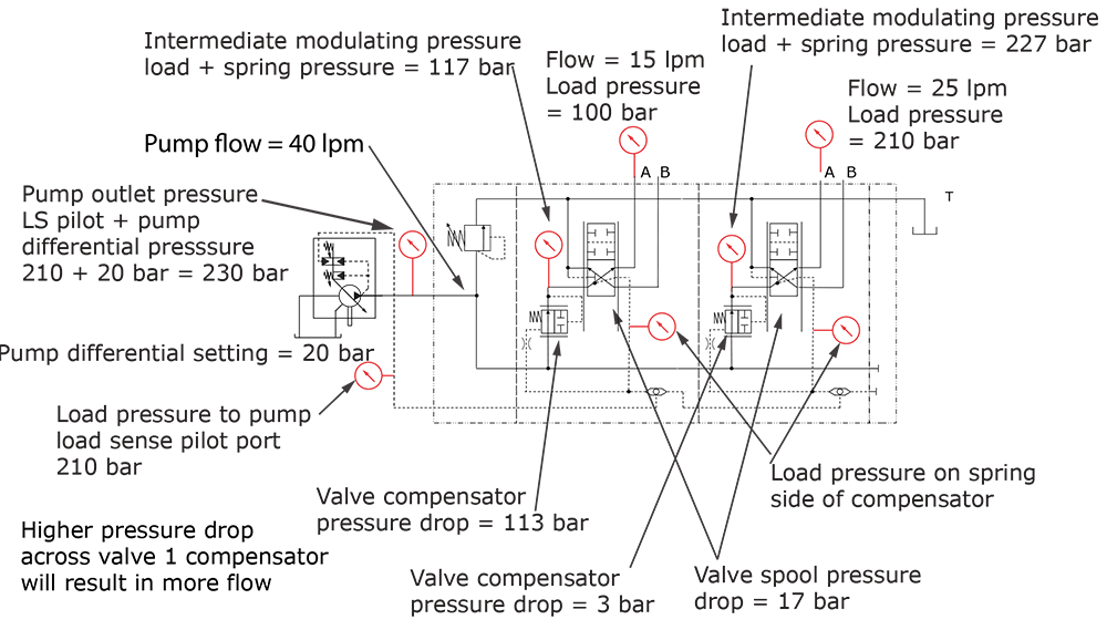
Figure 2b: Precompensation, both valves actuated.
As long as demand does not exceed the pump supply, both functions operate at their desired speeds, and the load-sense signal will be the highest load pressure value. Each valve section compensator will continually adjust to maintain a constant pressure drop across the spool it is sensing.
Figure 2c shows excessive flow demand. Hypothetically, if both functions are commanded to 100% simultaneously, both functions 1 and 2 require more flow than the pump can supply. As long as it has a lower load pressure, function 1 will get the full required 30 lpm (7.9 gpm), and function 2 will get the remaining 15 lpm (4 gpm). If function 1 flow command is reduced, function 2 will increase in speed. If function 1 is commanded to less than 20 lpm (5.3 gpm), function 2 will operate at full speed. In practice, since the function pressure may change based on the supplied flow, the function speeds may not be consistent at full command.
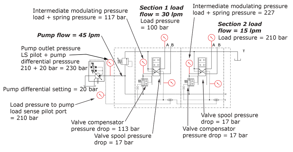
Figure 2c: Precompensation, both valves actuated, but inadequate flow.
In postcompensation, the compensator is a normally closed valve that opens when the pressurized fluid coming from the main spool pilots it open against a spring. The spring chamber is vented to the load-sensing line, which sees the highest load pressure. The pressure to open the compensator equals the spring pressure plus the highest load pressure. The net result is a consistent pressure drop across the main spool. Because the valve spool pressure drops are all the same, this arrangement has the advantage of restricting the flow to all work ports if the flow demand exceeds the capacity of the pump. All functions will slow down proportionally. The postcompensator arrangement is best suited for multiple working function applications requiring limited pump flow. It is not capable of accurate flow regulation due to the dependency on the pump’s load-sense differential pressure setting, also commonly referred to as margin pressure.
In the postcompensation circuit shown in figure 2d, using the same values as the precompensator examples: pump flow maximum is 45 lpm (11.9 gpm). Note: The load-sense differential setting of the pump is 20 bar (290 psi). Function 1 maximum is 30 lpm (7.9 gpm), 100 bar (1,450 psi). Function 2 maximum is 25 lpm (6.6 gpm), 210 bar (3,045 psi). Function 1 is commanded to 50% flow, which is 15 lpm (4.0 gpm). Since the pump can provide more flow than needed, both valve sections will receive the correct flow. The compensator sections are sensing pressure upstream and downstream of the spool valve. The pressure drop across each valve spool is the same. The load pressure does not affect the compensator modulation. The highest load pressure is being sensed at the pump. As long as the valves do not require more flow than the pump can provide, the performance will be the same as the pre-compensated valve.
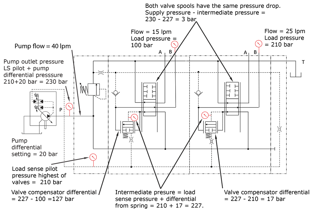
Figure 2d: Postcompensation, example 1.
In the postcompensation circuit shown in figure 2e, if both valves are commanded to 100%, the flow demand exceeds the pump output. Because the individual compensator sections maintain the same pressure drop across the valve spools, the flow will be proportionally reduced, so the functions of both sections will have reduced speed. When using compensated valves with load-sense pumps, it is recommended to set the pump load-sense differential pressure setting higher than the valve compensator setting. In the examples shown, load-sense differential pressure setting was 20 bar (290 psi), and the valve compensator was 17 bar (246 psi).
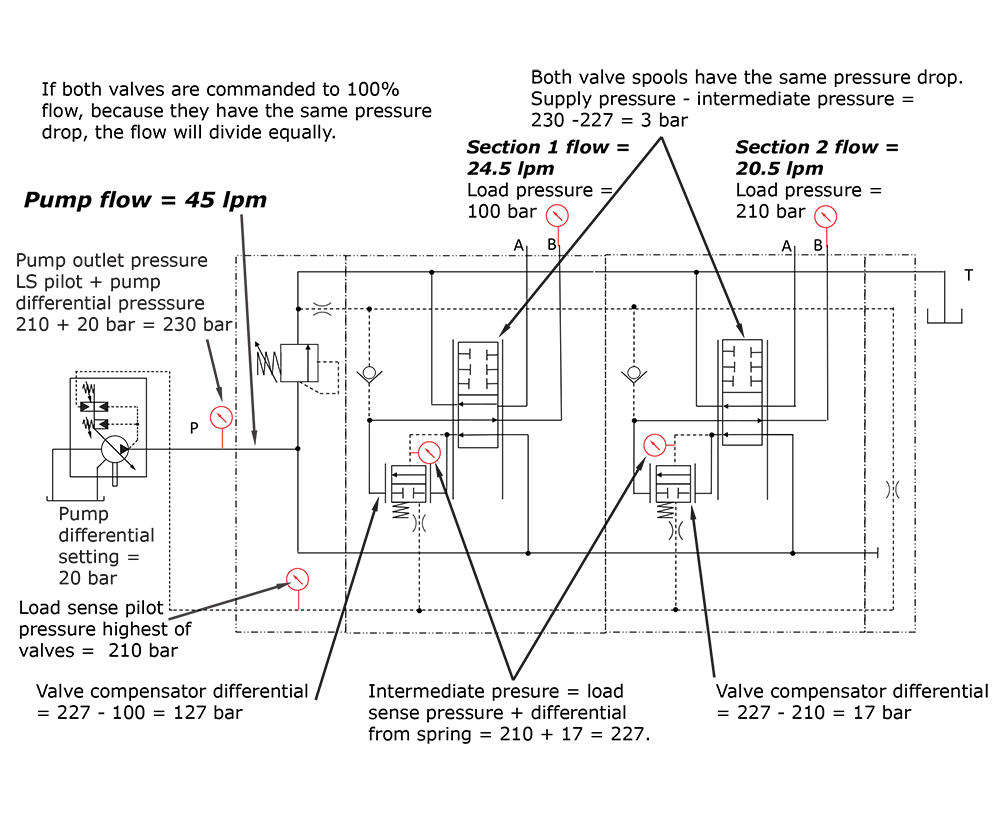
Figure 2e:- Postcompensation example 2.
Test Your Skills
1. A mobile valve:
a. is not suited for industrial applications.
b. is not limited to mobile applications.
c. has a high leakage rate.
d. must be used with load sensing.
e. has a low pressure rating.
See the Solution
Share this information.
Related Posts


Sponsor

Sponsors