Test Your Skills: Replacing Hydraulic Valves
Even though hydraulic valves are relatively simple devices, often with only one or two moving parts, close attention needs to be paid when replacing them. Subplate-mounted solenoid-controlled valves can have a variety of spool conditions and solenoid voltage options. Even though the replacement valve may physically fit in place of the original valve, the function can be different and result in a potentially hazardous unintended movement when the machine is started. Mobile-style sectional valves not only can have different spool configurations but also multiple other options. These options can be in the individual valve sections as well as in the inlet and outlet sections. Cartridge-style valves, both the common cavity style that conforms to an ISO standard and valves that fit a proprietary cavity, can be flow control, directional control, or pressure control that fits into the same cavity. Cartridge valves may have the same mounting thread but a different cavity profile to accommodate the three or four flow paths compared to a simple two-flow path cavity. The extra paths connect to a third drain or pilot port. The same mounting thread can also fit a four-way directional valve or pressure valves with both separate drain and pilot ports with different cavity profiles.
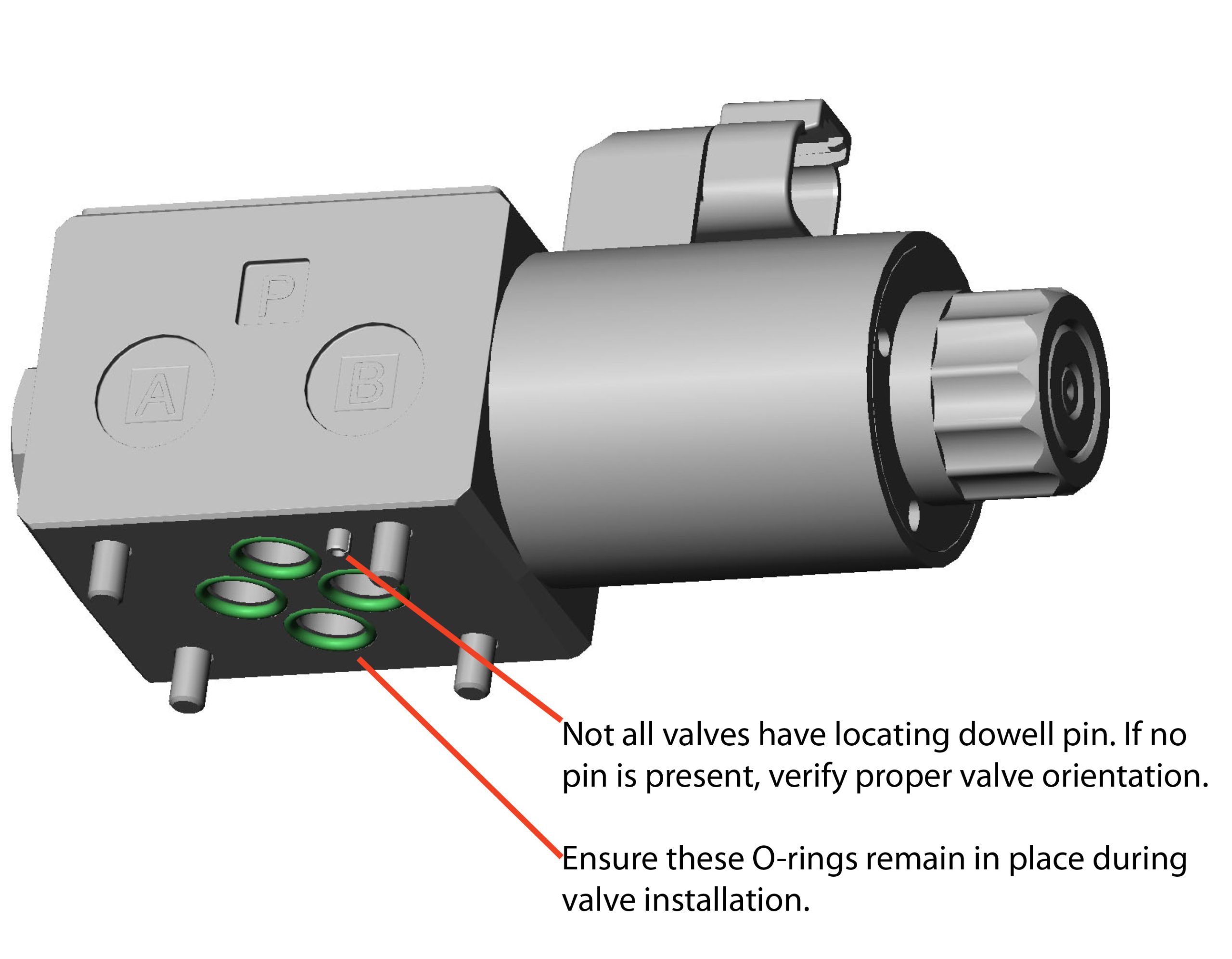
When replacing any valve, all the O-rings should be replaced. Carefully inspect the mounting surface or cavity once the old valve has been removed to confirm the old seals have also been completely removed.
It is important when installing a new valve that the manufacturer’s torque specifications are followed. Be sure the proper mounting bolts are used, as the use of incorrect bolts may affect valve operation (see drawing below).
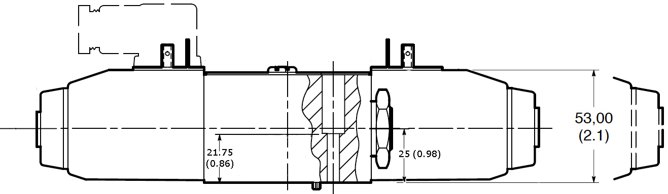
Valve installation drawing.
In the drawing, note that the shoulder where the mounting bolt head rests is below the centerline of the valve to minimize the chance of spool binding due to uneven torque applied to the mounting bolts. When installing a new valve, special attention must be paid to ensure any O-rings remain in place and are not cut or pinched during the installation process. The O-rings should not be installed dry. A common practice is to use a small amount of hydraulic fluid, grease, Vaseline, or retaining compound specifically designed for retaining O-rings. Ensure the material is compatible with the O-ring material and the hydraulic fluid (see illustration).
Identifying the valve to be removed from a machine can be difficult, if not impossible, due to paint applied after the valve was installed, a buildup of dirt, or physical damage to the data tag. The repair manual or bill of materials should also be consulted. The part number of the replacement valve should match exactly with the valve to be replaced. Even a single digit change in the model code can indicate a significant difference, such as an open center versus closed center valve.
Before removing the old valve, the machine must be put into a safe state, with all supported loads lowered or blocked with a suitable support. Suitable containment must be in place. If shut-off valves exist, they should be closed to reduce fluid loss, but they must be opened again before starting the machine. Any hoses or tubes that are removed should be capped to minimize spillage and prevent introducing dirt into the hydraulic system.
Load-holding valves require special attention when being serviced. One manufacturer’s counterbalance valve pressure setting is increased by turning the adjustment counterclockwise, unlike most other pressure controls that increase the setting by turning the adjustment clockwise. Field adjustment of the setting on counterbalance valves is not recommended, especially if there are two parallel cylinders with counterbalance valves that move the load. Equipment builders may specify nonadjustable counterbalance valves to prevent improper or mismatched settings. Cylinders with integral dual counterbalance valves may have different settings for extend and retract. Identifying which counterbalance valve controls the extend or retract function may be difficult to determine without details of the cylinder plumbing.
Pilot-operated check valves do not have spring adjustments but may have an adjustment or manual override that will permit manually opening the valve without pilot pressure present.
Test Your Skills
1. Why would a counterbalance valve be used that is nonadjustable?
a. Internal drain prevents valve adjustment.
b. Valve is pressure balanced.
c. Pressure is adjusted by second pilot.
d. Prevent improper or mismatched field adjustment.
e. Spring adjustment would interfere with check valve.
2. When replacing a cartridge-style valve, the replacement valve:
a. Must exactly match the old valve.
b. Can be shorter, as long as it fits into the cavity.
c. May not have an adjustment screw because it is factory set.
d. May have a solenoid instead of an adjusting screw indicating it is proportional.
e. Will have the same function as long at it has the same number of ports.
See the Solutions
1-d and 2-d
Share this information.
Related Posts

Sponsor

Sponsors