Test Your Skills: Sizing and Selecting Vacuum Pads
Vacuum pads are primarily used for handling smooth-surfaced material but can be used with textured or irregularly shaped material as well. Because sheet glass and other products that have a smooth surface generally have few to no places for attaching mechanical hooks and grippers, vacuum pad technology enables the material to be efficiently and safely moved.
Because of the many applications for using vacuum pad lifting technology, and the many possibilities of surfaces and working environments encountered, vacuum pads come in various shapes, sizes, and materials to allow a wide selection range.
The principle behind vacuum pad technology is simple. The area of the pad multiplied by the pressure applied results in a holding force. The pressure within the pad is less than atmospheric (vacuum). The differential pressure between atmospheric and the vacuum level within the pad is the effective pressure against the area of the pad contacting the surface of the material. This results in a force holding the material to the pad. The pad is attached by placing it against the surface and then drawing a vacuum. The force required to pull the cup away from the surface is proportional to the vacuum and size of the pad. The higher the vacuum, or larger the vacuum pad, the stronger the pull force required to detach the vacuum pad.
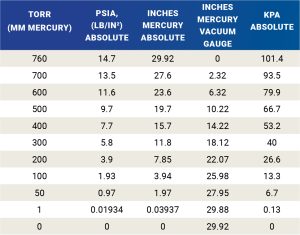
If the vacuum is provided in units of negative pressure (-psi or -kPa) then the calculation is the standard formula for force. If the vacuum is provided in a different unit of measure, the simplest solution is to convert the units to the equivalent negative pressure first.

Note: Chart is referenced to sea level.
Proper selection of vacuum pads is much more involved than the simple pressure-times-area calculations. The effective force used in the calculation must include the acceleration forces in all directions in addition to the weight of the workpiece. The interface between the vacuum pad and the workpiece is not a 100% seal. The accepted practice is to add a safety factor to the load based on the orientation and direction of movement. For applications that include only static holding, a safety factor of 2:1 is acceptable. Vertical lifting and horizontal movement (which are shear forces) should use a minimum safety factor of 4:1. If the vacuum pads are positioned horizontally with the workpiece positioned vertically a minimum safety factor of 8:1 is recommended.
Example 1: The combined force for lifting and moving a workpiece is 24 pounds.
The vacuum is 7.8 in-Hg absolute (200 torr).
The oval-shaped pad has dimensions of 3 inches x 1 inch.
Using a minimum safety factor of 4:1, how many pads should be used?
Use atmospheric pressure of 14.7 psia.
Solution
Calculate pressure difference between atmospheric
conditions and the vacuum:
1 in-Hg = 0.491 psi
7.8 • 0.491 = 3.83 psia
Pressure differential = 14.7 – 3.83 = 10.87 psi differential.
Calculate the area of the vacuum pad. The area of an oval pad is found by multiplying the major radius by the minor radius then multiplying by pi (π):
The oval pad has dimensions of 3 x 1 inch.
The major radius is 1.5 inches and the minor radius is 0.5 inches.
Area = 1.5 • 0.5 • π (3.14)
Area = 2.36 inches
Calculate the force of one vacuum pad:
F = p • a = 10.87 • 2.36 = 25.65 lb per pad.
Total force (required including safety factor) = 96 lb
Number of pads = 96 lb / 25.65 lb per pad = 3.74 pads.
Number of pads required = 4.
Example 2: What is the lifting capacity of a quantity of 10 vacuum pads, each with an effective diameter of 30 mm using a vacuum of -55 kPa? The recommended safety factor is 8:1.
Solution
Calculate the total area of the pads.
Each pad = 30² • 0.7854 = 707 mm².
Total area = 10 • 707 = 7,070 mm².
Calculate the theoretical lifting force.
(55 • 7,070) / 1,000 = 388.85 N.
Determine lifting capacity including safety factor.
388.85 / 8 = 48.61 N.
The surface of the workpiece will affects the quantity and profile of the vacuum pads that should be used. Multiple pads distribute the force to prevent damage due to deflection. Multiple pads also provide an additional margin of safety in the event of a pad’s failure. Pads that have a bellows or oblong shape provide for a better sealing surface on rounded or uniquely shaped parts. The surface of the workpiece influences the pad’s material. Softer materials form a better seal to reduce the amount of leakage, but they are subject to more wear. Residue of the workpiece manufacturing process and temperature also influence the material selection. Other considerations that should not be overlooked are nonmarking and antistatic requirements.
Using pivoting ball mounts at the interface between the vacuum pad and the tooling, the vacuum pad can be positioned perpendicular to an oddly shaped workpiece. Nonrotating mounts ensure that oval-shaped pads maintain proper orientation. Mounts with springs permit greater positioning flexibility. An example would be a transfer line that removes product from a stack. As the stack height is reduced, the spring takes up the movement, rather than adding an actuator to sequentially lift the stack, or a complicated control that either monitors the height of the stack or the number of parts transferred, to reposition the height of the pad.
A vacuum check is a simple solution to ensure that a momentary loss of vacuum will not cause the part to drop. However, it may hinder the release of the vacuum once the process completes. Additional circuitry may be required, including redundant systems applying vacuum from separate vacuum generators to multiple pads.
The actual application of the vacuum pad has many other unknowns that cannot be easily identified. Excessive dust or inconsistent surface finishes affect leakage that adversely impacts the vacuum level. Before approving the final design, the fixture must be extensively tested with several different workpieces to ensure proper long-term operation.
Test Your Skills
1. With a flat piece of sheet metal that weighs 100 lb and with atmospheric pressure at sea level – using 4 circular vacuum pads that each have a diameter of 4 in. What is the minimum required vacuum needed for static holding, with standard safety factor of 2:1, on each cup?
a. 10.2 in-Hg gauge.
b. 26 in-Hg absolute.
c. 8.1 in-Hg gauge.
d. 14.7 psia.
e. 700 torr.
2. What is the equivalent pressure of 300 torr in kPa (a) absolute?
a. 40.0 kPa (a).
b. -45.3 kPa (a).
c. 56.0 kPa (a).
d. -56.0 kPa (a).


