Pneumatic Versus Vacuum Component Design
By Dane Spivak, Engineering Manager, Davasol Inc.
A pneumatic system is defined as an application that uses a positive pressure gas to perform an operation. A typical air compressor can generate over 100 psi greater than atmospheric pressure. Since atmospheric pressure at sea level has an expected value of 14.7 psi, pneumatic systems have available pressures of many multiples of atmospheric pressure. A vacuum system is one in which gas is removed to create a pressure lower than atmospheric pressure. Therefore, theoretically, the maximum available vacuum pressure at sea level is -14.7 psi relative to atmospheric pressure. This is a state of “perfect vacuum,” in which all gas and matter are removed from the system. It is referred to as absolute pressure.
The key takeaways from the above paragraph are that pneumatic pressures are many multiples higher than vacuum, and that pneumatic pressure is a pressure greater than atmospheric, while vacuum is less than atmospheric. These two differences play a significant role in the design and implementation of their respective components.
Before we discuss components, it is important to understand flow and pressure losses within fluid power. No system is perfectly sealed, so leakage is a relatively common occurrence. Using the appropriate components can provide near zero leakage, which is the common goal of most applications. Leaks affect pneumatics and vacuum much differently. Consider a situation in which a fitting is leaking in both a pneumatic system and a vacuum system, resulting in a pressure drop of 2 psi for each. Although 2 psi may seem fairly insignificant, a vacuum system is much more impacted. The table below shows the comparative results of these losses when vacuum has a 15% drop in pressure, compared to the pneumatic drop of 2%.
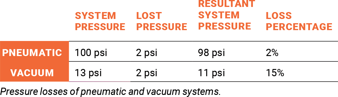
Above all else, pneumatic systems are designed for air consumption, as most applications are frequently exhausted during cycles, such as with pneumatic actuators. Leaks, losses, and use are essentially an expectation and built into the system design. On the other hand, users expect vacuum systems to be nearly perfectly sealed, and the vacuum pump is sized according to this logic. Therefore, small leaks in vacuum could have a much larger impact.
For the component analysis, a good introduction is to start with the basics of fittings, tubing, and hose. Many of these parts are interchangeable within pneumatics and vacuum, though there are subtle design differences that play an important role.
Push-to-connect fittings are the preferred connection technology for air systems for tubing a half-inch and smaller. Push-in fittings are functionally designed for pneumatic applications, though not all are suited well for vacuum. The primary reason is the internal O-ring that seals against the tubing. Figure 1 shows two fitting models with different O-rings. The fitting on the left has a standard round O-ring, while the fitting on the right has a flap shape. Under positive pneumatic pressure, tubing expands, and both seals would work well. However, under vacuum, the tubing would collapse slightly. This could result in potential leaks with the rounded O-ring, but the flap style would push out and compensate to maintain an airtight seal.
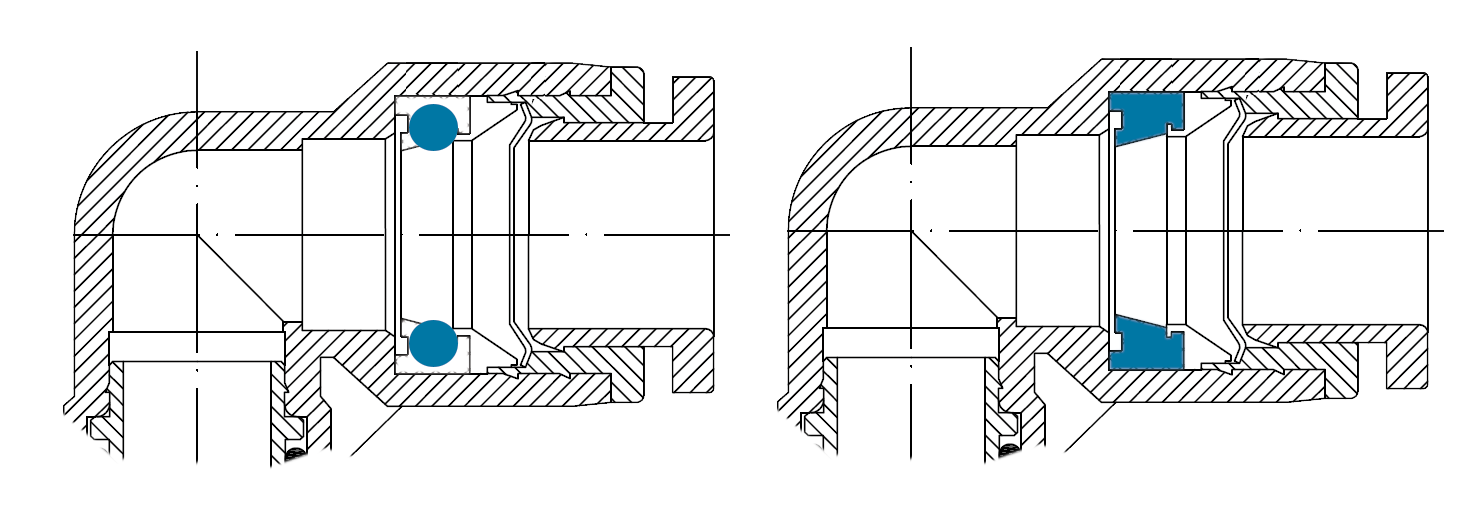
Figure 1: Round and flap-shaped internal O-ring designs for push-to-connect fittings.
Generally speaking, all pneumatic tubing of a half-inch and under is used for vacuum as well. Arguably, harder tubing would be ideal as it seals more confidently with push fittings and collapses less to maintain maximum cross-sectional flow areas. But for the most part, these concerns are negligible or nonexistent if the components are specified and installed correctly. A difference worth noting is a preference for clear tubing in vacuum systems to help identify any build up or blocks in the lines. This is a more frequent occurrence in vacuum due to lack of point of use or prefiltration.
Fittings larger than a half-inch often play in favor of vacuum, since a typical connection would be made by press fitting the inner diameter of a hose over top of a barbed fitting and clamped down. In this scenario, vacuum would suck the hose end down onto the fitting, resulting in a tighter fit, but pneumatic pressure would push it outward by expanding the hose.
Unlike tubing of a half-inch and under, larger hose reacts much differently under pneumatic and vacuum pressure. Because of the larger diameters, there are greater forces being applied to the hose (see figure 2). Pneumatic hoses often have mesh reinforced walls, which adds strength to combat the outward pressure inside the hose. However, the mesh design does not handle vacuum pressure well and tends to collapse the hose, restricting the flow of the system. Coiled reinforced hose is preferred for vacuum for this reason. It is ideal, as the coil shape provides the needed support of atmospheric air pushing the hose from the outside diameter due to the vacuum state within. Much like tubing, clear hose is preferred for vacuum to have a visual of the internal lines.
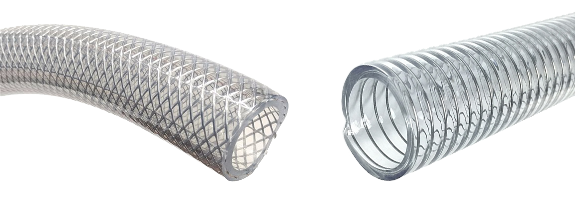
Figure 2: Mesh pneumatic hose versus coil vacuum hose.
Filtration units and systems are common in most fluid applications. In pneumatics, compressor manufacturers often suggest very fine centralized filtration, from 1 micron to as low as 0.01 micron. The finer filtration allows for cleaner systems and exhausted air, which is a benefit for maintenance and safety. The nature of compressed air pressure allows for ease of pushing through finer filters of reasonable physical sizes and without negatively impacting the compressor or system performance.
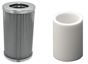
Figure 3: (Left) 40-micron and (right) 0.01-micron elements.
Vacuum filtration is quite different, as a 5-micron filter element would be regarded a finer porosity. Figure 3 shows the difference between filter elements. Lower micron ratings could either restrict the flow or require a filter too large relative to the rest of the system. Given that most vacuum components and pumps can operate well under these filtration conditions, vacuum filter ratings are in the 5-to-40-micron range for a typical industrial application. However, finer and specialized filtration is applicable to certain vacuum applications. It is important to note that pneumatic and vacuum filters are often not interchangeable. Using the wrong filter could result in restricted flows, system leaks, or improper filtration altogether.
Control valves in pneumatics and vacuum each have their unique design features. Many pneumatic valves are internally piloted, meaning there needs to be compressed air inside the line to help the valve power and move positions. This is the typical design for the common spool valves found on pneumatic manifolds. The concept is efficient for pneumatic controls but, of course, would not work under vacuum.
Since internal pilot valves would not work under vacuum, external piloted models are a popular design choice. As the name suggests, an external pneumatic source helps power the valve and shift positions. With this design, both vacuum and pneumatic pressure in the system would be accepted since the external pneumatic source helps control the valve as a separate function. Figure 4 illustrates internal and external pilot valve models with the external pilot port indicated by the arrow.
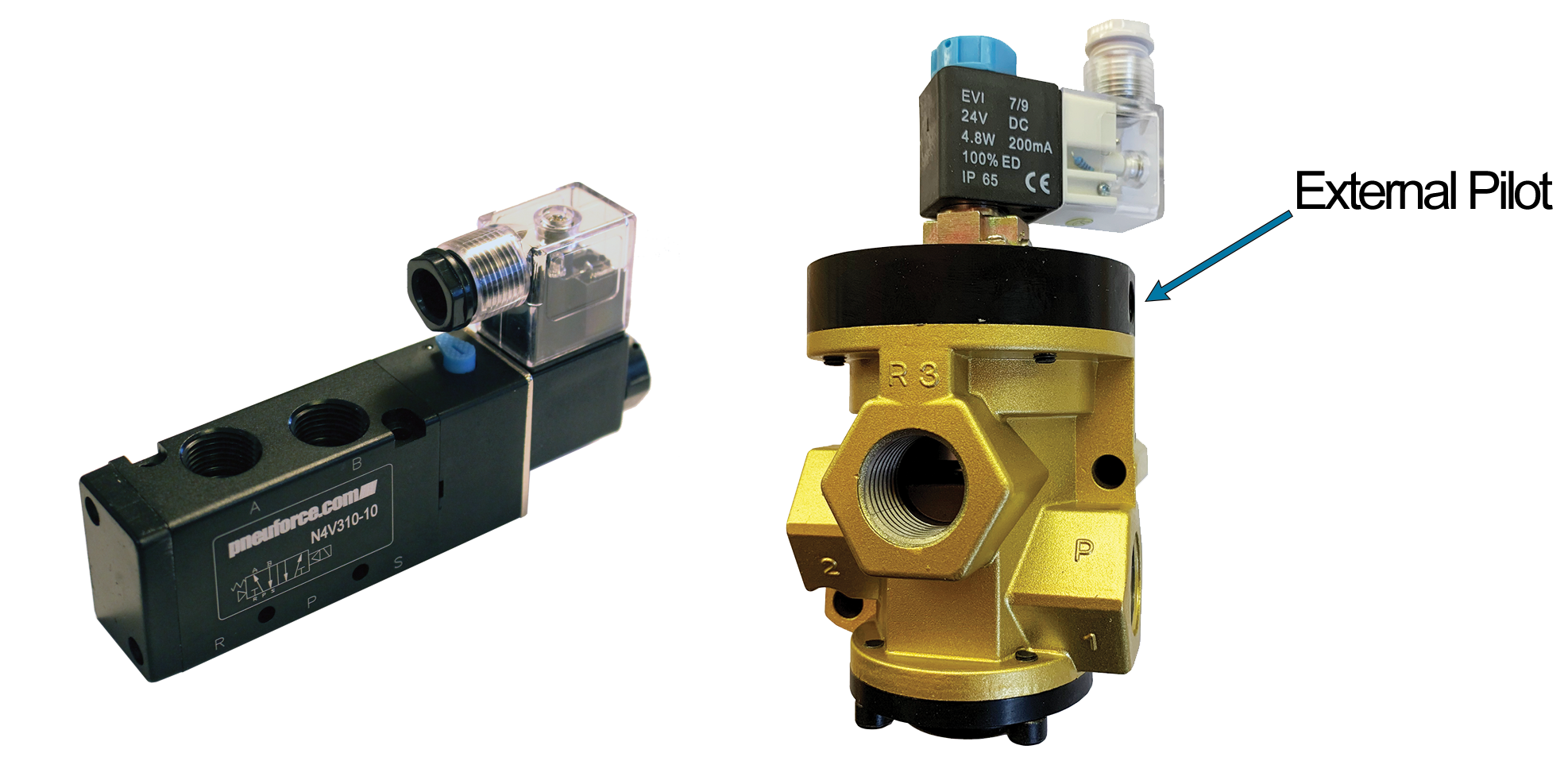
Figure 4: (Left) internal and (right) external pilot valves.
Direct-acting valves work when pure electrical energy from a solenoid controls the valve position with no other form of assistance. Direct-acting valves can work for both pneumatics and vacuum. But depending on the valve design, vacuum may require significantly more power. Figure 5 shows a cross-sectional view of a direct-acting normally closed poppet valve. The normally closed condition means the valve is closed at its rest position and opens when powered. Under pneumatic pressure, the valve seat pushes upward and helps the valve remain open when powered on. However, under vacuum, the pressure attempts to suck the seat back down and close the valve. For this reason, vacuum valves often require larger solenoids and more power to open valves. Some small direct-acting valves may work under both pneumatic and vacuum conditions, but the dual compatibility becomes increasingly difficult with larger sizes, since more force is applied to the valve seat. Therefore, larger direct-acting poppet vacuum valves have much larger coils than their pneumatic counterpart.
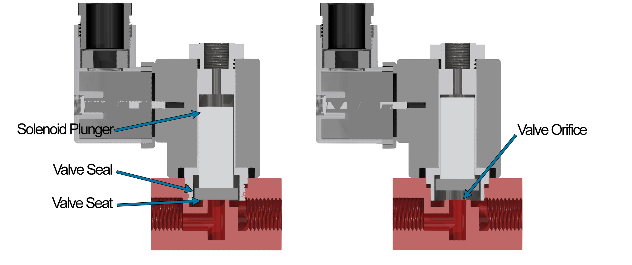
Figure 5: Cross-sectional direct-acting poppet valve.
As with many components, compared to pneumatics, vacuum requires larger flow-through areas, and that is no different when it comes to valves. Valves designed specifically for vacuum usually have much larger orifices. Even if a valve is considered vacuum rated, the orifice size and flow capacities should be understood to ensure it works well with the system as a whole. The same would apply to pneumatics, of course. Additionally, the manufacturer should confirm that the valve models are specified for pneumatic and vacuum pressures. Although theoretically a valve should work, the internal designs may experience leaks or damage.
This article touched on many design considerations for pneumatic and vacuum components, including fittings, tubing, hose, filtration, and valves. It was intended as a conceptual analysis only. Automation manufacturers and design defaults often favor pneumatics, so it is imperative to understand the functionality and specifications of each part in a vacuum system. Every application is unique and professional assistance is always recommended.
Share this information.
Related Posts


Sponsor

Sponsors