Test Your Skills: The Difference Between Isothermal and Adiabatic Conditions
Hydraulic accumulators use weights, springs, or gas pressure to generate the precharge force against the fluid that is stored for use in the system. Gas-charged accumulators use pistons, bladders, or diaphragms to separate the hydraulic fluid from the gas charge. Bladder type accumulators are available in sizes ranging from 115 cc (7 in3) to 300 liters (80 gallons), generally in pressure ranges of 21 MPa and 35 MPa (3,000 and 5,000 psi).
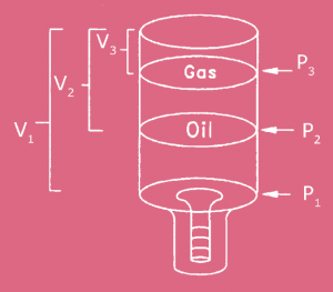
Gas-charged accumulators operate by placing the compressible gas over the nearly incompressible hydraulic fluid in a constant volume pressure vessel. The hydraulic pressure and volume of fluid available to the system are dependent on the precharge pressure and the expansion characteristics of the gas. Dry nitrogen is typically used to precharge accumulators.
The terms “isothermal” and “adiabatic” are used to describe the expansion characteristics of the gas. Compressing and decompressing gas causes it to heat and cool respectively. If the volume of the gas is changed slowly, the changes in temperature are dissipated through the solid materials of the accumulator and so the temperature of the gas is kept constant. This is called isothermal (same temperature) contraction and expansion.
When a gas is compressed and expanded quickly, heating and cooling cause pressure changes in addition to those occurring strictly as the result of volume changes. If the gas is insulated so that very little heat can escape, the pressure of the gas will increase and decrease more than inversely to the change in volume. Under compression, heat added to the gas as it is compressed will raise the pressure above the pressure increase caused by reducing the volume. Under expansion, the pressure will decrease more than would be expected just by decreasing the volume. This is called adiabatic (cannot pass) contraction and expansion.
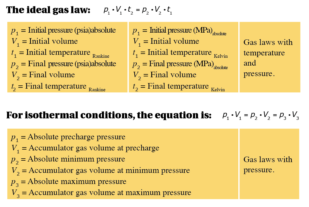
To accommodate changes in both pressure and temperature of the precharge gas, the general gas law can be used to compute the volume available from an accumulator. Absolute values are used for temperature and pressure when making computations. Rankine is the absolute scale for Fahrenheit and Kelvin is the absolute scale for Celsius. Formulas for converting from Fahrenheit to Rankine and Celsius to Kelvin are as follows:
°F to °R: °R = °F + 459.7
°C to K: K = °C + 273.15
Temperature has an effect in the application of accumulators. The ideal gas laws tell us that for a given change in temperature, there will be a corresponding change in the pressure within an accumulator. This makes temperature a necessary consideration when sizing an accumulator. If the ambient temperature changes, the gas temperature in the accumulator will also change and will affect the pressure. For example, an accumulator on a piece of equipment that is outdoors may have a much different ambient condition in the early morning than it will have in the heat of the day. The designer must be sure that the accumulator will be adequately sized to address these conditions.
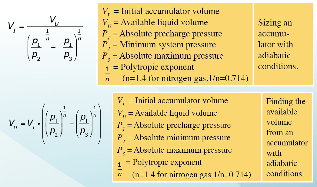
In general, charging the accumulator can be considered an isothermal process and the normal operation of the accumulator considered an adiabatic operation.
The following equations are for adiabatic conditions when solving for accumulator sizing or available volume:
Safety tip: A charged accumulator has stored energy. The uncontrolled release of that energy can cause serious injury, either by direct contact with pressurized fluid or the unexpected and uncontrolled movement of a machine. It is absolutely essential that the energy be drained or isolated before any work is performed on or around the accumulator. This means that the pressure of the hydraulic fluid must be isolated or brought to zero gauge or be isolated from possible unexpected release. A gas-charged accumulator must also have the gas pressure brought to zero gauge or isolated from unexpected release.
Safety tip: Releasing the gas charge will displace the air around the accumulator. If this is done in a small area, there is the danger of asphyxiation. Be sure the area is well ventilated or that the gas is vented to the outside.
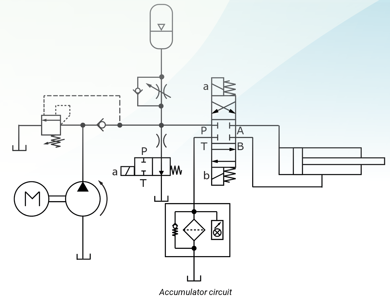
The closed-center accumulator circuit shown above helps to maintain system pressure. It could also supplement pump flow to operate the cylinder. Maintaining system pressure with the accumulator and closed-center valve makes the circuit more responsive. The accumulator will also supplement pump flow to supply more fluid than the pump alone could during brief periods of high usage. When the cylinder deadheads and the directional valve is actuated, the pump refills the accumulator. Pressure will pilot open the unloading valve, unloading the pump, while the accumulator makes up fluid lost due to system leakage. When the fluid in the accumulator has been depleted and pressure falls below the setting of the unloading valve, the unloading valve will close, directing pump flow into the circuit and also refilling the accumulator. Theoretically, very little flow will ever pass over the relief valve. The line to the accumulator is equipped with a free-flow check valve allowing unrestricted flow into the accumulator and an adjustable orifice in parallel with the check valve to control flow from the accumulator to the circuit. Without the needle valve, the cylinder speed would be dependent on the discharge rate of the accumulator, which can be much greater than the flow rate required by the application.
The fixed displacement pump fills the accumulator while the directional control valve is in the center position or when the cylinder is bottomed out when the valve is still shifted. Once the set point of the unloading valve has been reached, the unloading valve directs unneeded flow from the pump to the reservoir. Shifting the directional control valve releases the fluid in the accumulator and routes it to the cylinder. The pump remains unloaded as long as the accumulator can supply fluid to the cylinder at a pressure above the setting of the unloading valve. As the pressure drops, the unloading valve closes and the pump powers the cylinder, and given time, refills the accumulator. Maximum system pressure is controlled by the setting of the unloading/relief valve. The internal pilot would operate the relief valve should the external pilot become inoperative. As a safety measure, the 2/2 normally open solenoid valve releases pressurized fluid, through a small orifice, when the system is turned off. The check valve prevents downstream fluid from passing to tank when the unloading valve is piloted open.
Test Your Skills
1. A 4-liter capacity accumulator supplies fluid to a hydraulic system between 12 MPa and its precharge pressure of 6.9 MPa. Using the ideal gas law, how many liters of hydraulic fluid are available from the accumulator if the temperature changes from 27 °C to 65 °C as the accumulator fills? Assume adiabatic compression and expansion of the gas.
a. 0.4 liters.
b. 1.4 liters.
c. 2.1 liters.
d. 4 liters.
e. 5.5 liters.
 2. A 2-gallon accumulator supplies fluid to a hydraulic system between 3,000 psi and 2,000 psi. If the precharge pressure is 1,000 psi, how many cubic inches of hydraulic fluid are available from the accumulator if the process is isothermal as the accumulator fills?
a. 77.2 in3
b. 81.4 in3
c. 155.5 in3
d. 180.6 in3
e. 232.7 in3
See the Solution
1.b, 2.a
Share this information.
Related Posts

Adding Hydraulic Fluid to the Reservoir

Test Your Skills: Calculate the Oil Flow Rate & Pressure From a Pneumatic Intensifier
Test Your Skills: Understand the Application of Hydrostatic Systems

Stopping a Load with a Shock Absorber

Understanding the Selection Process of a Pressure Control Valve

Determining the Cause For A Cylinder Not Extending
Sponsor

Sponsors