Test Your Skills: Understand the Application of Hydrostatic Systems
The typical hydrostatic transmission consists of a closed circuit where a pump provides flow to a hydraulic motor without the use of directional valves. The ports of the pump are connected directly to the ports of the motor so that the flow from the pump drives the motor, and the discharge from the motor feeds the inlet to the pump. There are a number of valves included in the transmission package, but the main flow paths between the pump and motor are not restricted. The direction and speed of the motor is controlled by the flow from the pump. A bidirectional pump will provide a bidirectional motor. The pump and motor may be combined in a common housing or connected by plumbing when the motor is at some distance from the prime mover. The transmission produces a speed-torque ratio equal to the ratio of the motor and pump displacements. The motor can be a high-speed low torque, or a low-speed high torque design. Fixed or variable displacement pumps and motors can be used to match the need of the application (see table).
A common pump assembly consists of a hydromechanical, servo controlled, variable displacement, axial piston pump that is biased to zero displacement, with overcenter capabilities that allow it to vary and reverse the flow between the main two work ports while having a constant direction of input rotation. The pump assembly also includes a replenishing pump (sometimes referred to as a charge pump), a replenishing relief valve, and two replenishing check valves. The replenishing pump is typically 10% to 20% of the main pump displacement, although some applications may require greater replenishing displacement. The pump assembly may include ports to permit filtration of the replenishing flow and additional servo control valves.
There are several ways to provide input to the servo displacement control: manually with a lever or linkage controlled by the operator, hydraulically using remote pilot pressure, or electrically using a proportional solenoid operated pressure reducing/relieving valve.
Overpressure protection is accomplished by cross-port relief valves, a pressure compensator control that overrides the displacement command, or a combination of the two functions (figure 1).
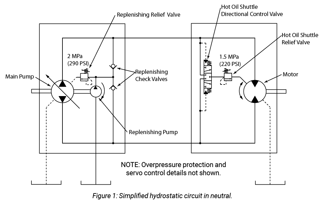
A hot oil shuttle package may be attached to the pump or motor or plumbed into the main work ports as an independent valve manifold. The hot oil shuttle package consists of a 3/3, closed center, pilot operated, spring centered, directional control valve and a low-pressure relief valve. The purpose of the hot oil shuttle is to allow some of the oil from the motor return to be directed to tank so additional fresh replenishing fluid will be forced into the pump. This is necessary because the volume of fluid in the operating loop is usually a small fraction of the flow rate. In large systems, the fluid volume may be 1/10 of the flow rate. In close coupled pump-motor combinations, the ratio will be significantly smaller. Operating inefficiencies will quickly overheat the working fluid if it is not replaced by cool replenishing fluid (figure 2).
During operation, when the main pump is in neutral at zero displacement, no fluid is flowing out of or into the main pump ports. The motor is not turning. The replenishing pump is pressurizing the two work ports via the replenishing check valves to the pressure setting of the replenishing relief valve and providing flow for the servo control mechanism. The surplus fluid of the replenishing pump is flowing through the replenishing relief into the pump case and out the case drain back to the reservoir. It is best to filter the replenishing fluid before it enters the main flow loop.
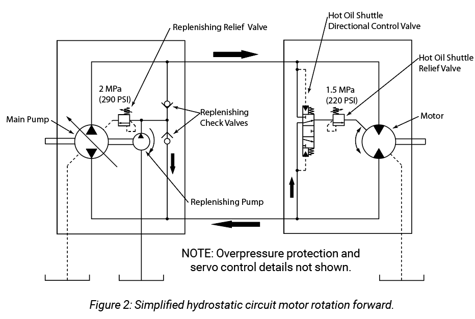
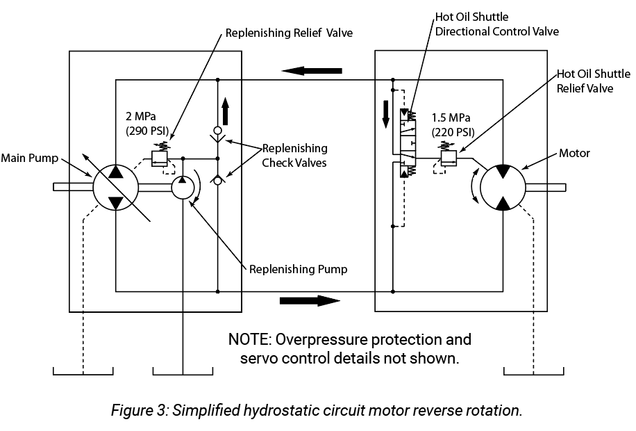
When the operator provides a displacement command to the pump, the flow produced causes the motor to rotate in the direction and speed proportional to the command. The load resistance causes the pressure in that work line to increase. The differential pressure between the two work lines causes the hot oil shuttle valve to shift, connecting the low-pressure work line to the hot oil shuttle relief. The hot oil shuttle relief pressure setting is slightly lower than the main pump replenishing relief valve. This causes the surplus replenishing flow to be exhausted out of the main flow loop through the hot oil shuttle valve assembly. Due to the relative locations of the replenishing check valves and the hot oil shuttle valve, oil from the replenishing pump is drawn directly into the main pump. The same amount of oil is diverted out the hot oil shuttle valve. The remaining motor return oil is combined with the replenishing pump flow to insure the main pump has adequate flow to prevent cavitation. The pressure on the return side of the main loop will be at the pressure setting of the hot oil shuttle relief valve. Reversing the operator displacement command will cause the motor to rotate in the opposite direction, the hot oil shuttle valve will shift in the opposite direction due to the differential pressure being inverted. This process ensures that a constant flow of cool filtered oil is being introduced into the main flow loop and the heat and contaminants picked up are flushed out. The return line from the hot oil shuttle valve may be routed through the motor case, and is usually directed through the filtration and cooling part of the circuit (figure 3).
Dynamic braking occurs when the load being driven has a high inertia and the displacement command is reduced. For example, if the displacement is reduced from 100% to 50%, the lower pump flow will cause the driving pressure to drop. However, because the motor is still rotating at the higher speed, the load inertia will try to drive it as a pump. Because the pump now has a lower displacement, it will not accept the high rate of flow, causing the pressure to increase on the return side of the motor to the pump. In this example, the pressure increase multiplied by the motor displacement will produce a braking effort to the motor shaft. The same pressure increase multiplied by the new pump displacement of 50% will cause the pump to develop an output torque on the shaft, effectively putting energy back into the power source. In the case of a conventional induction electric motor, the electric motor becomes a generator and puts the power back into the grid. In the case of a diesel engine, the engine will defuel and the hydrostatic drive will power any other components connected to the diesel. If the overrunning energy is too great and the tare engine load is too small, the diesel could be oversped because of the diesel engine’s limited ability to accept overdriving loads. The magnitude of the dynamic braking is dependent on the inertia-drag of the load and how quickly the pump displacement is reduced. Slowly ramping the displacement down may not cause any dynamic braking because the drag of the load will slow it down at the same rate.
Brake or counterbalance valves should not be used in a hydrostatic circuit because the heat generated is more than the replenishing circuit can easily dissipate. If brake valves must be used because of safety or other reasons, the replenishing flow will need to be increased to insure adequate loop cooling. If the hydrostatic drive uses cross-port relief valves for overpressure protection, stalling the motor at full pump displacement will quickly cause the system to overheat and result in severe damage to the components in a matter of seconds. The pump output flowing across the relief valve at the maximum setting will be converting 100% of the input power to heat. Because of the small volume of fluid in the loop, the high temperature oil will immediately flow through the pump and have its temperature increased as it again flows through the relief valve.
When used in vehicle propulsion, two or more motors in parallel will act as a differential. The hydraulic flow will divide proportionally to the motors as the vehicle turns. Should one motor lose traction and have minimal load resistance, all the flow from the pump will try to pass through that motor. Some means of a flow divider or other antispin device may be required.
TEST YOUR SKILLS
The amount of torque that a fixed displacement motor can produce in a hydrostatic transmission is:
a. Dependent on the input rpm of the hydraulic pump.
b. Higher in the forward direction than in the reverse direction.
c. Increased as the replenishing pressure is increased.
d. Dependent on the motor displacement and the maximum pressure setting of the cross-port relief valves.
e. Dependent on the pump displacement and the maximum pressure setting of the cross-port relief valves.
See the Solution
Correct answer is d.
Share this information.
Related Posts
Sponsor

Sponsors