The Overlooked Usefulness of Vacuum Gauges & Switches

The following article was written by Dane Spivak of Davasol Incorporated, an industrial brand management firm with many clients, one of which is Vacuforce LLC based in Indianapolis USA which this article is written in partnership with. Its intent is for conceptual examples only. Contact Dane Spivak by email at dspivak@davasol.com.
One could argue that the most important piece of information in a fluid power system is pressure. Using simple measurement devices such as pressure gauges allows the user to understand performance and identify abnormalities within a system. Furthermore, switches may be used as a gauge, and as a device to signal controls to perform actions as a result of the pressure measurements. The following article will discuss how gauges and switches can be implemented in industrial vacuum systems to benefit the user.
Gauges seem to be less common in vacuum systems compared to other fluid mediums. Perhaps because of the low pressures, designers feel vacuum is a lesser threat to workers and the application environment. If a hydraulic system has sudden increases or drops in pressure, alarm bells would ring, figuratively and possibly literally, and the necessary steps would be taken. With vacuum, a similar situation may go unnoticed from an automation perspective since the potential consequences are perceived to be much less significant. However, without vacuum pressure readings it may prove to be difficult to identify and localize issues when they arise.
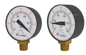
Figure 1 – Vacuum gauge at rest and at 25.5inHg
Figure1 shows a picture of a vacuum gauge at rest and at 86.35 kPa (25.5inHg). At rest, the gauge shows a reading of 0 kPa (0 in Hg) which is atmospheric pressure that has a mean value of 101.38 kPa (14.7psia) at sea level. This is an equivalent reading to 0 kPa (0 psig) at rest on a pressure gauge. In North America, vacuum gauges in industrial use typically display units of inHg (inches of mercury) and bar (a non-standard unit equal to 100 kPa) though other units such as Torr (millimeters of mercury), in H2O (inches of water), or kPa (kilo Pascal) are available. Note that the gauge needle indicator rotates in a counterclockwise direction to indicate that it is a “negative pressure” which is better described as a pressure lower than atmospheric. A vacuum gauge cannot indicate if a positive pressure is exerted in the system as the lowest point is atmospheric pressure. To detect a positive pneumatic pressure, a secondary pressure gauge can be used, or there are compound gauges which measure both vacuum and pneumatic.
Gauges are a simple cost-effective method to obtain a quick visual understanding of system status. For a relatively small system in a point of use application, using a single gauge is sufficient. If we consider a vacuum venturi and single cup gripping a product as shown in Figure 2, the vacuum gauge gives us a good measurement of the vacuum level throughout the small volume as losses are near zero. This way, if the system begins to run at 85 kPa (25 in Hg), but some time later it drops to 51 kPa (15 in Hg), we know that it is not performing at its intended vacuum level. From there, preventative maintenance steps may be taken such as replacing the cup if it no longer seals properly, or cleaning/replacing the vacuum inlet filter or venturi.
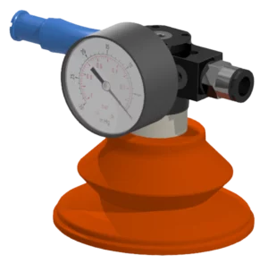
Figure 2 – Vacuum venturi coupled to a vacuum cup and gauge
In vacuum gripping applications there can be multiple contributing systems as shown in Figure 3 where the same system in Figure 3 is repeated to grip one part. Each venturi and cup assembly would be considered their own system as they are independently operated by their own vacuum venturi generator source. In this case, a vacuum gauge on each assembly would be recommended to understand how each individual system is performing. Systems may vary in performance, so using only one vacuum gauge on a single system may provide some form of vacuum level data but not adequate information for the whole application. Revisiting our previous example, one venturi may be achieving 85 kPa (25 in Hg) while all the others have experienced losses down to 51 kPa (15 in Hg). Realistically this is an unlikely occurrence, but conceptually important to consider.
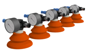
Figure 3 – Multiple vacuum systems in the same gripping application
Larger and more sophisticated vacuum systems experience losses, leaks, and consequently vacuum level variances. For this reason, more than one gauge is recommended in such a system. A good rule of thumb is to have one gauge close to the pump and the other close to the application. Figure 4 demonstrates this concept in a pick and place circuit. The gauge close to the pump is crucial in understanding if the pump is producing desired vacuum to begin with, and the gauge near the cups gives indication of the final vacuum level at the application. In a well sealed and appropriately designed vacuum system with reasonable hose or tubing length, minimal vacuum level differences would be observed. But it is not uncommon to see noticeable vacuum pressure differences between the two gauges from leaks or losses. Sometimes pressure differences can be deliberate in a vacuum system where a lower vacuum level is desired at the application. Understanding the vacuum level needs of the pump and at the application are important to establish from the beginning. However, the bottom line is as long as the application runs smoothly there is no reason to tinker around to absolutely maximize vacuum level and reduce losses unless considerable amounts of energy is wasted in the process.
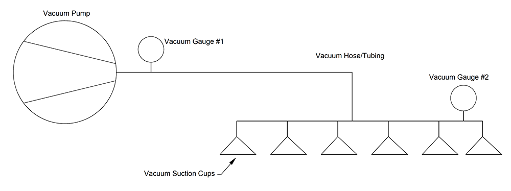
Figure 4 – Gauge locations at the pump and application
There are circumstances in which more than two gauges offer useful information in a vacuum system. Consider a large centralized system shown in Figure 5 where a vacuum pump powers multiple applications, one of which uses a vacuum regulator. In this system four gauges can be used: at the pump, before the regulator, after the regulator, and at the application. This way the pump vacuum performance can be understood along with the losses through the vacuum line to the regulator, the vacuum regulator functionality can be verified, and the application vacuum level can be monitored. This would allow an understanding of overall performance of this system section at each key point and identify problematic areas should vacuum issues occur. Figure 5 is a visual schematic that is not to any particular scale. However, considering that larger centralized systems may have relatively long vacuum lines in different shapes and sizes, impactful vacuum losses may occur.
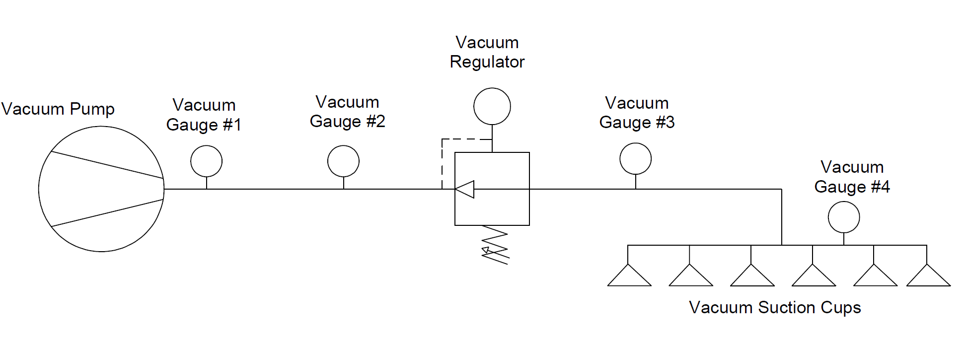
Figure 5 – Centralized vacuum system with four gauges
Now that we have grasped an understanding of where to measure vacuum and the information it can provide, we can consider how to automate solutions for repeatability, preventative maintenance, and safety. Using vacuum measurements alone, vacuum switches are the common method in accomplishing the aforementioned.
There are two popular types of vacuum switches in industrial automation: electromechanical and electrical solid-state. An electromechanical switch has a simple design. There is a vacuum level setting which may be preset or adjusted depending on the design. Based on the vacuum set point, the electrical circuit is either opened or closed where the closed setting completes the circuit to send an electrical output. Electromechanical switches are available in normally open (NO) and normally closed (NC) options which dictates if the circuit is open (off) or closed (on) at its rest position. Figure 6 shows a normally open switch preset to 34 kPa (10 in Hg). This switch would remain open and have an off signal between 0-34 kPa (0-10 in Hg). Once the vacuum level is equal or greater than 34 kPa (10 in Hg), the switch circuit closes as the electrical contacts connect to complete the circuit to turn the signal on. The electromechanical switch is not as accurate or precise as a solid-state switch, but it is a simple cost-effective indicator. It is particularly useful for part presence in pick and place applications to signal controllers that vacuum has been achieved and the part has been gripped by the vacuum cups.
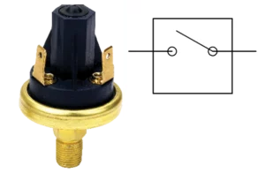
Figure 6 – Normally open vacuum switch
Electrical solid-state switches operate differently. Without getting into the electrical design aspects, the solid-state switch operates by pressure “disrupting” voltage differentials and providing electrical outputs as a result. Since this switch is not mechanical, it offers longer life, better accuracy, and resistance to vibrations. Additionally, electrical switch models may include LED screens, vacuum readings, and programmable units. Figure 7 shows an example of an electrical solid-state switch with these features.
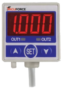
Figure 7 – Electrical solid-state switch with LED screen
Solid-state switches are used to monitor vacuum levels in a system to ensure consistency. They can also be used as a safety device such as ensuring an adequate vacuum level is reached during a pick and place application. It allows the control system to understand when a safe vacuum level and gripping force is met before proceeding with a movement cycle. Another example of a safety application would be to use a switch when power is lost to monitor vacuum level loss. If power is lost while a vacuum gripping system is at 85 kPa (25 in Hg), and safety shut off valves are in place, vacuum may be sealed and “trapped” in the system. Naturally, air will leak into the system and the vacuum level would lower over time. A switch can be used by setting a low point such as 68 kPa (20 in Hg) to take preventative measures once the vacuum level drops below this value.
Another type of useful vacuum switch is the pneumatic vacuum switch shown in Figure 8 where the switch (right) is connected to a pneumatic pilot valve (left). For this switch, the output signal is a pneumatic source. So, it essentially operates like the electromechanical type but sends an air signal instead. A pneumatic signal could allow direct control of a pilot operated valve or vacuum venturi as an example. It proves useful for compressed air energy savings with venturis and vacuum on/off controls.
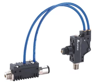
Figure 8 – Pneumatic vacuum switch
This article covered location points for gauges and how to implement switches in vacuum systems. Vacuum measurement is undeniably a major factor in understanding system performance and implementing the right components in effective areas allows for superior repeatability, monitoring, and safety.
Share this information.
Related Posts


Sponsor

Sponsors