Transformation Complete

Fluid power has become a vital component in our ability to perform work: it harvests our crops, takes our waste to the landfill, moves the landing gear, entertains and protects us, and all with a power density and flexibility that is unmatched in any other power transfer system. However, when it comes to efficiency, fluid power systems are not very high on the list. This article series will ask us to think differently about our fluid power systems. We will look at energy in a different way and discover ways to transform fluid power energy to make our systems more efficient, and then be able to make better use of the new and improved components available to us.
I’m not really saying it’s like a butterfly emerging from its cocoon, but I kind of like the metaphor. The lowly, often neglected, displacement flow divider is about to morph into something new that can dramatically change the way we think about and apply fluid power.
In “Flow Means ‘Go’… Well Not Exactly” (September/October 2016 issue), we discussed the need to think differently about the relationship between pressure and flow.
In “My Torque Isn’t Working” (Tech Directory 2016 issue), we discussed combining volume, flow, and pressure so that they can be viewed in terms of energy units or units of power. We then saw how this would aid in our qualifying and quantifying the efficiency of our fluid power systems.
In “If Motors Could Torque” (November/December 2016 issue), we re-examined the power formula to allow RPM to be the controlling factor. We saw how a properly controlled, variable-displacement motor could maintain a controlled RPM under varying loads without the use of a restrictive flow control. Multiple motors under continuously varying loads, being supplied from a common source, would each only draw the energy needed for the work being done at each moment.
In “Divide and Conquer” (January/February 2017 issue), we looked closely at the old technology of the displacement flow dividers, which we dubbed “pressure/flow transformers.” We saw how they can consume less energy than restrictive flow dividers because all the energy is being used to either do work directly or to assist in driving section(s) that carry a greater load. We also saw how they inherently divide and combine the energy units of flow and pressure. This is good for the synchronization of actuators, but also allows for pressure intensification and flow augmentation.
Thinking in terms of “flow means go,” we usually think of flow as controlling speed. We often interchange the terms of “speed control” and “flow control.” We need to think differently. When we control the speed of an actuator, we are really providing power control. Increasing the speed of a constant load means increasing the rate at which we supply energy units. We looked at this in detail when we used the variable-displacement motor with RPM control. To adjust the speed under a constant load, we changed the input rate of energy units. It is important to note that there needed to be a variable energy source, as well as a variable-displacement actuator to make this work efficiently. However, most fluid power applications do not use variable-displacement actuators. Most motors, and all cylinders, have a fixed volume for each revolution or stroke.
Now, a pressure/flow transformer is not really a flow control; it is a flow divider/combiner. It splits or combines flow in proportion to the ratios of the displacement sections. This is why some people refer to them as “flow proportioners.” They do not limit flow, but merely proportion whatever flow is passing through. What is needed is a way to use the transforming powers of the pressure/flow divider to mold the transfer of energy in a way that will provide true energy control, not just flow control.
What is emerging out of its historical cocoon is a new displacement device that enables us to let each actuator draw only the energy units needed for the work being done. When we think of power as a rate of energy unit input, we can see how controlling that energy can provide speed control without the use of restrictive flow controls.
Introducing the Variable-Displacement Transformer (VDT)
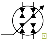 The VDT is simply a single, two-chamber, positive-displacement device with the displacement of each chamber dependent on the displacement of the other. It is placed in the fluid stream in such a way as to divide or combine energy units, much like the pressure/flow transformers in the previous article, only with infinite variability. It can proportion the energy into a 100% to 0% ratio, a 0% to 100% ratio, or anything in between. The suggested symbol in Fig. 1 shows a single rotary device with two chambers. Each one is dependent on the other, and each one can be driven by or drive the fluid energy passing through it. It is also infinitely variable.
This is valuable, even if it is only used as an adjustable flow divider for use in synchronizing actuators with varying displacements. But there is much more that can be done with this device. We can use it as an actuator speed control. It can allow us to limit the energy units taken from the source to what is actually needed for power.
In application 8) Regeneration Two-Speed Motor Circuit in the “Divide and Conquer” article, we showed the simple 50/50 pressure/flow transformer providing two speeds from a motor. In that circuit, a resistive load on the motor drove the transformer. Half the energy went to the reservoir and half was added to the input of the motor, increasing the speed but reducing the torque. Now we will look at a similar circuit using the new VDT (Fig. 2).
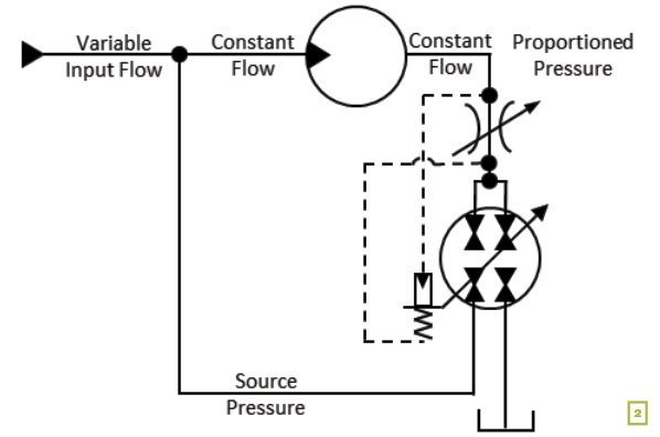
Here we have a variable-flow source, either from an accumulator or a pressure-compensated pump. The motor has a fixed displacement, and we want it to run at a constant RPM. There is a varying load on the motor. The default condition of the VDT is for 100% of the flow to be directed to the reservoir. When the motor starts, the full source pressure is directed to the motor so it has full starting torque. The output from the motor passes through a hydrostat that responds to a differential pressure across an adjustable orifice. As the motor reaches the desired RPM, the upstream pressure balances against the control spring. If the motor begins to exceed the desired RPM, the pressure differential increases, shifting the VDT to send a portion of the flow back to the motor. The flow from the source is reduced so that only the energy units needed to drive the motor are used. If the load increases, the motor will try to slow down. This signals the VDT to send more of the flow to the reservoir, reducing the backpressure and increasing the torque, satisfying the power formula. The VDT allows us to use full pressure all the time by reducing the flow from the source. Only the energy units needed are drawn from the source.
Some of you may have noticed that there is a restrictive orifice in the circuit. I was hoping you wouldn’t bring that up, but now that you mention it… Actually, the VDT is designed so that the pressure drop across the orifice is only about 5 bar. This is much less than the pressure drop when using a pressure-compensated pump, which must be set at the highest system demand plus about 15 bar. It is also much less than the energy loss when using accumulator pressure. As a matter of fact, it is only about 1/3 of the energy lost in load sensing. If we want to remove the restrictive energy loss completely, we could replace the orifice with a proportional solenoid and let RPM control the motor through the PLC.
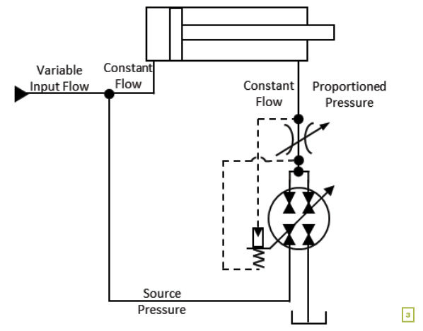
A very exciting application is when we use the same arrangement with a cylinder. In application 7) Regeneration Two-Speed Cylinder circuit, we showed the simple transformer regenerating flow. When we use the VDT, we have the effect of using a variable-displacement cylinder (Fig. 3). The VDT system produces a resistive pressure just like a meter-out, pressure-compensated flow control. But instead of squeezing off the extra energy and disposing of it as heat, the VDT redirects the energy to do useful work. This cylinder is able to have a constant change in energy draw throughout its stroke.
One of the things we do well in fluid power is store energy. With hydraulics, we use accumulators. In pneumatics, we use receivers. Where we tend to do poorly is when we release that energy to do work. The VDT eliminates that problem. It now becomes very practical to store energy, even at very high pressures, and then release it as energy units for the work instead of pealing off the pressure as heat.
Using the VDT or the variable-displacement, RPM-controlled motor are ways in which we can really reduce the energy waste in our fluid power systems. Both systems allow a central power source to supply multiple units, with each actuator only drawing the energy units needed. The VDT has the advantage of being able to be used on both motors and cylinders with fixed volumes. The VDT can be placed in the return line from a directional valve to provide energy control bi-directionally. Even some electric motors can be replaced with a more efficient fluid power system when those motors are oversized and/or see widely varying loads.
I have only hinted at the pneumatic applications. The VDT functions like a variable-displacement turbocharger with one outlet port open to atmosphere and the other to the supply line. Just like a meter-out flow control, the VDT applies the necessary resistive load, but instead of using up extra energy units, the resistance is used to help reduce the air consumption.
There are many more circuits we could draw, including some where the VDT is used at the inlet of an actuator where power can be used for either speed or force.
But for now, we have a lot to think about.
Dan Helgerson, CFPAI/AJPP, CFPS, CFPECS, CFPSD, CFPMT, CFPCC, is Fluid Power Journal’s technical editor. He can be reached at Dan@DanHelgerson.com. Keep the conversation going by visiting Dan’s blog, Watts It All About.
Share this information.
Related Posts
Pneumatics Gets a Grip on Robotic Tooling Applications
Vacuum Gripping and Pick & Place for Wood Surfaces

Is Your Air Compressor Control Smarter Than a Four Year Old?

Vote for Your Favorite Photo Now!
Without Skilled Tradespeople, Who Builds It?

The Crucial Role of Cleaning & Sealing Hydraulic Hoses & Tubes
2 thoughts on “Transformation Complete”
Leave a Reply
Sponsor

Sponsors
Dan,
Thank you for taking the time to write this series of articles on the unit of Power. Informative Where can someone find information on the VDT if they want to spec it into a system?
A number of people have asked this question. The answer is that, as of this writing, there are not any available. There are at least three versions that are at different stages of development, but none can be found at your local distributor. My next article (which I am behind on writing) discusses this issue and explains several ways in how you can make your own (DIY).
The fact that I am getting these questions indicates a certain success of the articles. I was trying to create an awareness of the potential and the need for such a device. We need to think differently and in so doing, develop circuits that use that thinking to help us be more efficient.