Troubleshooting & Testing Vacuum Systems
By Dane Spivak, Engineering Manager, Davasol Inc.
This article focuses on how to identify and fix issues within a vacuum system. The specific focus is on vacuum cup systems where cups are used to grip or lift a part. However, many of these concepts can be applied to different types of vacuum systems with air as the fluid medium.
 In a vacuum gripping system that is not performing as it should, it may be natural to look at the vacuum cups as the problem. Vacuum cups naturally wear away and lose their ability to seal on a cup surface. Or in another scenario, when testing a new system and the cups do not grip the product, again the cups are usually blamed. Changing out vacuum cups for new ones or switching to a different model that is better suited for sealing against the product surface is certainly an easy approach to a solution. And if it works, things carry on as usual and the problem is soon forgotten. However, if this quick fix does not work, there can be confusion over the next step. So let’s look at potential issues within vacuum systems and what can be done to test and establish a long-term solution.
The first thing to do is conduct a visual inspection of the vacuum system from the cups right back to the pump. Ensure that all fittings, tubing, and hose are connected securely. Airtight seals are very important in vacuum. Unlike compressed air, small leaks in vacuum can be significantly more detrimental to the system. See if anything could be potentially clogging or blocking the vacuum lines or components. This is much easier to do with clear hose and tubing, which should be used in vacuum systems if possible. Inspect the pump inlet filters to see if they are clean, and replace the element as needed. All these things could restrict vacuum flow or reduce the vacuum level, causing failure.
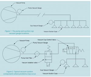
If the visual inspection checks out, then the vacuum level and vacuum source should be investigated. First, measure the vacuum level at or near the cups and at the vacuum pump. In an ideal system a gauge in both locations is installed, as shown in figure 1. If the vacuum levels are significantly different, it gives an indication that something is creating a change within the system. If both gauges show similar high vacuum levels, it indicates something is going wrong near the cups or the fundamental design does not work. If both readings are similar, reading a low or zero vacuum level, it means the pump is not working correctly or there is too much leakage in the system to generate a higher vacuum level.
Regardless of the gauge readings, the maximum vacuum level of the vacuum source should be understood. This can be accomplished by deadheading the pump, which is done by blocking the vacuum inlet port of the pump after the vacuum gauge and checking its vacuum level. This provides test results of an ideal situation in which the vacuum system is perfectly sealed, and the point of measurement is right at the production source. The deadheaded vacuum level should match closely with the pump-manufacturer’s data sheet. If there is a significant difference, the pump may require inspection, maintenance, or replacement. Deadheading to measure the vacuum level should be done with any new system or vacuum source to confirm it operates as it should.
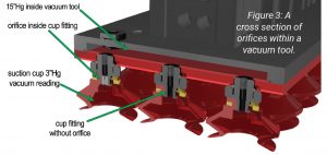
Let’s consider a situation in which both gauges read zero or low vacuum levels per the illustration in figure 1. After deadheading the pump and confirming it works as it should, we can rule out pump issues. That means the entire system is experiencing a loss in vacuum. This usually means the loss is due to leakage, as the pump cannot remove air faster than the air bleeding back in to create a lower pressure (vacuum). In this case, it is easy to start at the pump and work down the line to the cups since we know the pump is performing as it should. Start by checking for any clear leaks, which can be done by using nondamaging smoke or water mist near any potential problem areas. Remember to have vacuum turned on! The deadhead test can also be pushed down the line, and see where vacuum drops off to identify the problem area. Perform the vacuum-level test in stages and push the vacuum cut off point one component at a time if necessary. Figure 2 shows sections of a vacuum system where problem areas can be identified. If testing shows that the vacuum level is maintained up to the cups, it means either there is too much leakage at the cup sealing face and therefore a larger pump is required, or that a different system design should be considered.
If we revisit figure 1 and the gauge at the pump has a high and adequate vacuum-level reading but the gauge near the cups is low or zero, it tells a different story. It means the pump is producing a vacuum level, but somewhere between the two gauges the flow is restricted or stopped and therefore not allowing comparable vacuum levels to be achieved down the line. For a new system it is imperative to size up each component within the vacuum system so that it can allow the pump to produce its maximum flow throughout. If everything is sized correctly, check for restrictions by looking for problem areas where debris collection could occur, such as sharp turns, smaller orifice areas, or mechanical moving components. The obvious component to check is the vacuum valves to make sure they are opening to their full extent and working well. Confirm with the manufacturer that the valves are indeed vacuum rated and offer vacuum-flow capacities to meet the performance of the pump. If a problem cannot be identified or fixed, it means there is a flow restriction or leakage somewhere that has not been identified, or there are too many natural losses within the system due to the turns, bends, and lengths of the hose and fittings. Starting with the deadhead test and working toward the cups is always helpful to best understand the next step.
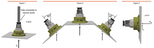
 Lastly, in reference to figure 1 again, if the gauges at the pump and near the cups show adequate vacuum levels as required and anticipated, the problem lies at the cups themselves or with the vacuum design. Figure 3 shows a vacuum tool populated with numerous cups. In this example, the vacuum gauge in the tool shows 15 inches Hg, but the vacuum level inside the suction cup is only 3 inches Hg. That is due to the restriction of the flow from the tool to the cup. The cup is not creating a good enough seal on the surface, which causes air to leak into the cup. The leaked air into the cup is then being restricted from the cup orifice into the tool. To avoid a drop in vacuum level inside the cups, use a larger orifice to increase the flow to the cup. At this point it is also worth considering a different type of cup to offer a better seal on the product surface. Taking an actual measurement of vacuum within the cup can be difficult because there often is not a plausible way to connect a gauge. There is always a way to get a measurement regardless of how rudimentary, but it’s not always necessary if the issue can be identified based on observation. If there are multiple cups tied into one vacuum source, it is easier as you can sacrifice one cup in the application by connecting it to a gauge, after the restrictive orifice, of course. The highest gripping force of the cups can always be tested by covering them all with a flat smooth part such as a piece of steel plate. Doing this can always help put things into perspective.
This article provided suggestions on how to troubleshoot a vacuum system. The key takeaway is to start off with the right design, but also have gauges or other vacuum-level measurement devices to monitor performance. Being able to identify problematic areas can be a tremendous time saver. Although these are what would be described as universal rules, each application can create its own set of challenges. Seek assistance from an experienced vacuum engineer to not only troubleshoot, but to provide a long-term solution.
This article is the opinion of the author, Dane Spivak of Davasol Inc., an industrial brand management firm with many clients. One of Davasol’s clients, Vacuforce LLC, based in Indianapolis, partners with the author on this article. Contact Dane at dspivak@davasol.com.
Share this information.
Related Posts
The Science of Vacuum-Cup Forces

Congratulations to Newly Certified Fluid Power Accredited Instructors!

Accelerating Performance: Seven Steps for Promoting Employee Engagement

Hallite Opens New Global Test House
Eaton’s IFPM Fluid Purifier Systems
Unlocking Efficiency: Vacuum Clamping for Diverse Applications
Sponsor

Sponsors