Under Surveillance: Testing Vehicle Steering and Fan Drive Systems
By Martin Cuthbert, Managing Director, Webtec.
Power-assisted steering is now common on all types of on-highway vehicles. While electric steering systems are gradually replacing traditional hydraulic systems on cars and other small vehicles, the steering forces required on larger vehicles (such as trucks and buses) still require the power capability of hydraulic or electrohydraulic systems in many cases. Pure hydraulic systems employ an engine-driven pump to provide the necessary flow and pressure, whereas electrohydraulic systems use an electric motor driven pump. In either case, the safety of the vehicle and its occupants obviously depends on a steering system that is operating to specification.
On-road vehicles normally retain a mechanical linkage from the steering wheel to the steered wheels, such that in the event of a complete failure of the hydraulic system, the vehicle can still be steered, albeit with an increased amount of effort on the part of the driver. This is why it is referred to as “power-assisted” steering; the hydraulic steering force simply assists the driver’s steering effort, reducing driver fatigue. Off-road vehicles, (where the steering effort required may be significantly greater) generally use true hydrostatic steering, in which there may be no direct mechanical linkage from the steering-control input (wheel or joysticks) to the steered wheels or tracks.
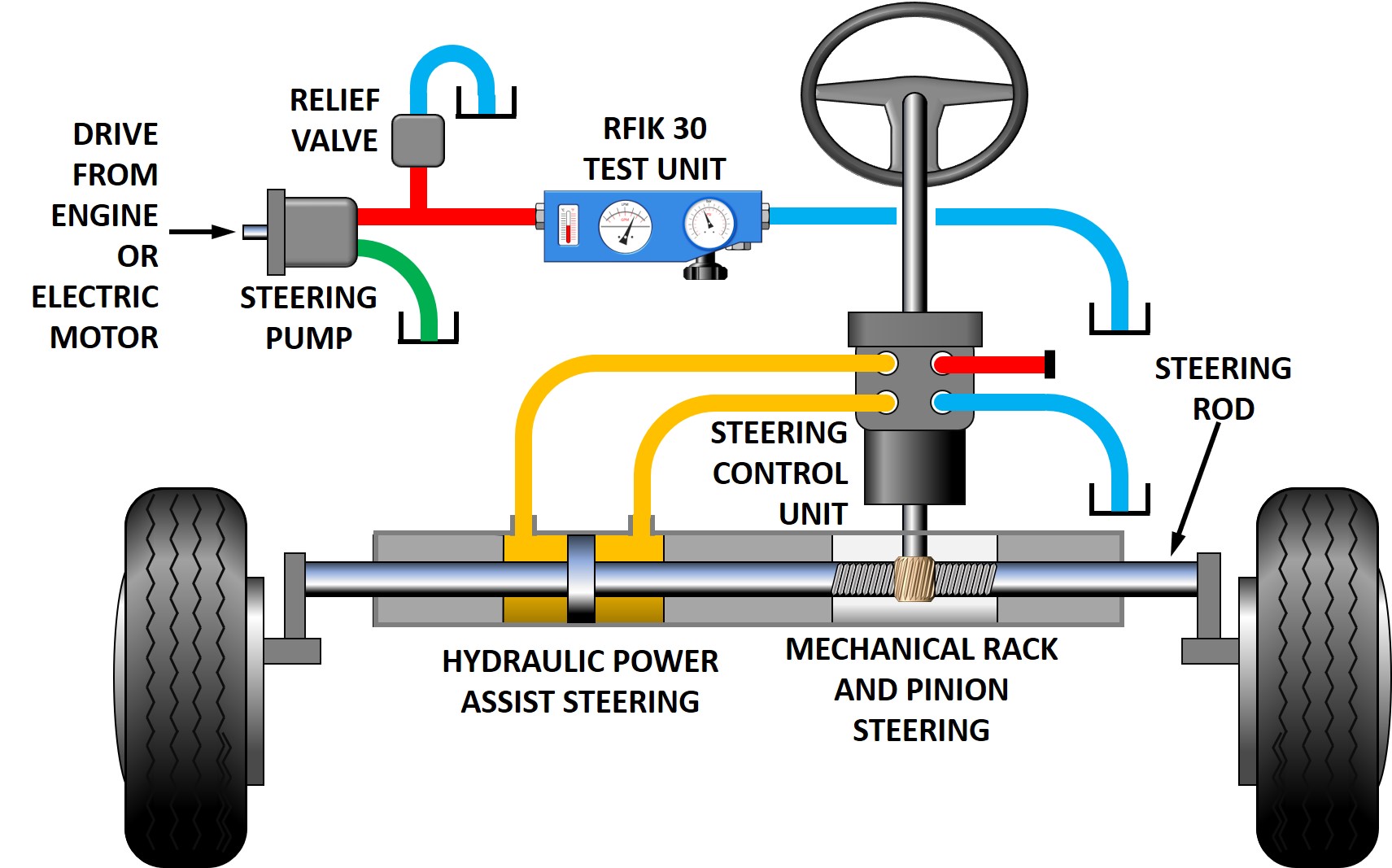
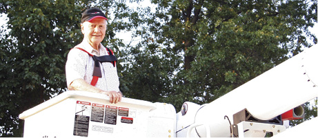
Installation of the RFIK 30 test unit.
As in many hydraulic systems, the pump in a power-assisted steering system is usually the component most susceptible to wear or damage, which, if overlooked, could result in complete failure and a consequent loss of the steering’s power assistance. Regular testing of the pump and its associated relief valve is therefore an important part of the vehicle’s maintenance schedule. Ideally, testing would be carried out with the pump in situ, but if this is not possible, then the pump can be returned to a service center equipped with a suitable test bench. In either situation, a reliable, simple-to-use test instrument can check both the pump flow and the relief-valve setting.
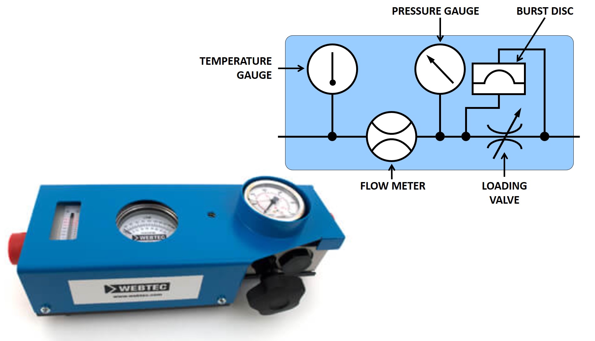
Webtec’s RFIK 30 test unit.
Pump flow rates in on-road vehicle steering systems are typically in the range 15 to 20 lpm (4 to 5 gpm) at pressures of approximately 170 to 180 bar (2,400 to 2,600 psi). The Webtec RFIK 30 test unit has a measurement range of 2 to 30 lpm (0.5 to 8 gpm) at pressures up to 420 bar (6,090 psi), so it is ideally suited for testing in which measured values are likely to be in the midrange of the test unit’s ratings.
As a pump’s wear increases, the clearances between components (and hence internal leakage) also increases. However, a worn pump may still produce close to its specified flow rate at low pressure when leakage rates are low. But the pump output flow is likely to reduce significantly as the pressure increases to its normal operating level. By incorporating a pressure-balanced loading valve in its design however, the Webtec unit is able to simulate normal system operating pressure at the pump outlet.
Fluid viscosity may also affect the amount of leakage from a worn pump, and viscosity in turn is affected by fluid temperature. To carry out the pump test under conditions as close to normal operation as possible, the fluid temperature and viscosity should be adjusted as required. Heating of the fluid occurs naturally as flow passes across the loading valve, and the built-in temperature gauge of the RFIK unit indicates when a suitable temperature has been achieved.
Installation location
Installing the test unit between the pump outlet and the vehicle’s steering-control unit, the pump flow rate can be checked against specification using the test unit’s flow meter. Closing off the loading valve adds resistance to the pump output flow, thus simulating the steering effort required under normal operation. The built-in pressure gauge enables the loading valve to be adjusted to ensure that the pump delivers the correct flow at its normal operating pressure.
To check the system relief-valve setting, the test unit loading valve can be closed further, increasing the pump outlet pressure to a point where the pressure no longer continues to rise. This then indicates the pressure setting of the system’s relief valve.
If the flow rate indicated on the test unit is less than the specified amount, then the pump may not necessarily be at fault. A reduced flow rate could also be caused by a leaking relief valve, an incorrect drive to the pump, or an incorrect motor speed if driven by an electric motor. Further investigation may therefore be required if a flow deficiency is discovered. The test unit is protected from overpressurization by means of a burst disc should the system relief valve fail to operate for any reason (but this is an unlikely situation).
Flow passing across the relief or loading valve at high pressure generates heat. With a relatively small reservoir the temperature of the system fluid can increase quite rapidly if the test process is prolonged. The RFIK test unit therefore incorporates a fluid temperature gauge that indicates when an excessive temperature level is being approached and testing should be paused. Also, when using a temporary pipe connection from the test unit to the system reservoir, take care to ensure that the reservoir fluid does not become unduly aerated.
Due to their larger size and greater necessary steering forces, off-road vehicles often use true hydrostatic steering, i.e., where there is no mechanical linkage from the steering wheel to the vehicle’s steered wheels. Such applications may require pump flows up to 200 lpm, in which case Webtec’s larger RFIK 60, 120, or 200 test units would be suitable.
Hydraulic fan drive systems
Recent legislation in Europe and the U.S. relating to vehicle diesel engine efficiency and emissions requires the engine to be operated within a narrow temperature range. Traditional means of cooling via an engine-driven cooling fan can often provide too much cooling at high engine speeds and may also generate insufficient air flow at slow engine speeds. Furthermore, an engine-driven fan requires the heat exchanger element (radiator) to be mounted close to the engine itself. Space requirements for heat exchangers can be significant. As a result, many on-road trucks and buses as well as many off-road vehicles now use hydraulic fan drive systems in which an engine-driven pump provides power to a hydraulic motor that drives the cooling fan.
This provides two main advantages. First, the cooling fan speed can now be modulated independently of engine speed. Temperature sensors mounted within the cooling medium identify when cooling is required. Information is transmitted, often via the vehicle’s CAN bus system, to a control unit that adjusts the oil flow to the fan drive motor via a modulating hydraulic valve. The fan drive speed is therefore directly proportional to the cooling requirement at any time, ensuring the engine operates within its optimum efficiency range and reduces parasitic losses caused by unnecessary fan operation. The power absorbed by the fan is proportional to its rotational speed cubed (double the speed requires eight times as much power), so power losses caused by unnecessary cooling at high engine speeds can be significant.
The second advantage is that the vehicle’s heat exchangers can be located conveniently where space is available and air flow is more easily managed.
If required, a fan reversing valve can also be installed in the system to periodically blow debris out of the heat exchangers. In some cases, the vehicle’s power steering or other auxiliary function pump can be incorporated onto the rear of the fan drive pump so that only a single power take off output is required for both functions.
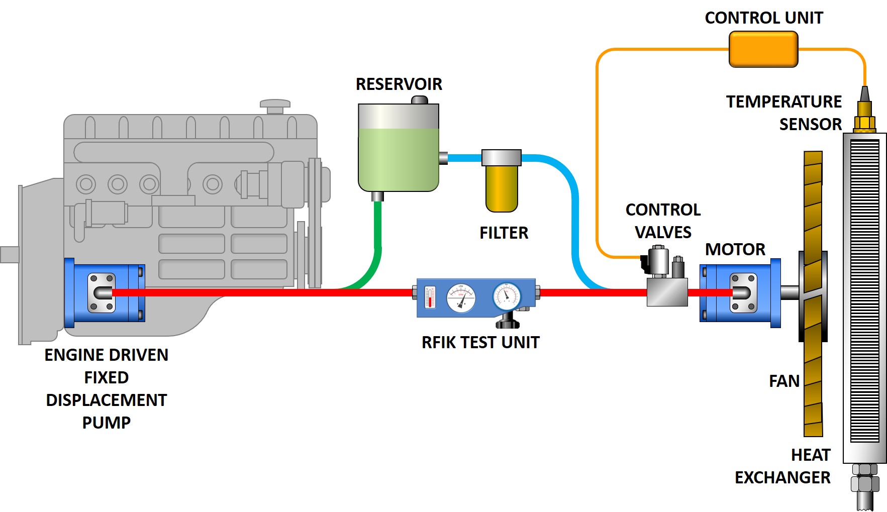
Figure 1: The test unit installed with a fixed displacement pump.
Depending on the power requirement of the fan drive, gear, vane, and piston pumps/motors are used, which in the case of piston pumps, may be either fixed or variable displacement.
For troubleshooting a fan drive system or during a vehicle’s scheduled service, the Webtec RFIK test unit can again be installed in the pump outlet line as shown in figure 1. The pump output flow depends on the engine drive speed, so consult the manufacturer’s service information to determine the appropriate engine speed for measuring pump flow. If the pump flow proves to be correct but the fan rotation speed is slow, then the problem is likely the hydraulic motor or any control valves between the pump and motor. Since pressure at the outlet port of the pump will be generated by the torque load of the fan during the test, the loading valve of the RFIK unit can remain fully open.
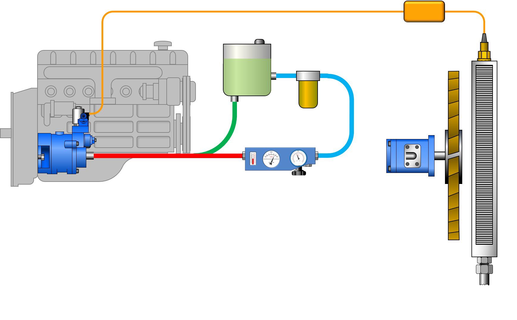
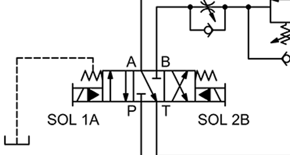
Figure 2: An alternative method of testing a variable displacement pump.
The flow output of a variable displacement pump depends on the engine speed and the controlled displacement of the pump between zero and the maximum. A common control arrangement is to electronically adjust the pump compensator setting in order to vary the fan speed, since the relationship between the fan speed and its required drive torque is governed by a cube law (twice the speed requires eight times the torque). So testing a variable displacement pump can also be carried out by installing the test unit, as shown in figure 2, where the test unit outlet is connected back to the reservoir, thus bypassing the motor.
After setting the compensator adjustment to its normal maximum pressure, the motor drive pressure can be simulated by closing the test unit’s loading valve. The pump flow rate can then be checked against specification up to its normal maximum working pressure.
The RFIK test unit’s ability to monitor flow, pressure, and temperature while simulating the normal pump working pressure can therefore be invaluable for online or offline testing of vehicle steering and fan drive pumps.
Share this information.
Related Posts


Sponsor

Sponsors