Unlocking the Potential of Hydraulic Flanges
A Comprehensive Guide to Specifications & Options
Empowering Industry Professionals with In-Depth Insights on Hydraulic Flange Standards and Selection
By Robert Mackey, MAIN Manufacturing Products Inc.
A hydraulic flange is an adapter that connects a flange pad of a component or other flange to some other connection. Money, time, safety, and design are being compromised due to a lack of understanding of the options available when specifying flange standards. Several times a week, we have users who do not understand the choices that are available when specifying hydraulic flanges. This article will discuss the ten items involved in specifying four-bolt hydraulic flanges and available options for each. These ten items are:
From the standard:
- Pad size (bolt pattern)
- Screw size and thread
- O-ring size
- Maximum rated working pressure (MRWP)
Additional items:
- Flange type
- Connection type
- Connection size
- Geometry
- Material
- Extras
The starting point is generally the component that the flange is attaching to, which gives the first 4 items that we don’t have control. The component is probably manufactured to a standard that specifies the mounting pad and the first 4 items in the list above:
- Screw size and thread- (although metric or inch screws will need to be specified)
- Bolt pattern
- O-ring size
- Maximum pressure rating
1. Pad size (bolt hole spacing)
The component that the flange attaches to might indicate the standard and size or bolt-hole pattern. Knowing the country of origin of the equipment can be helpful. Japanese equipment is more likely to be associated with a JIS pattern than ISO 6164, which is based on a German standard. Knowing the outside dimensions of the flange is often not helpful. Different manufacturing methods use different blank sizes. Many international standards use the abbreviations DN (nominal diameter) and PN (nominal pressure) as part of the size designation. Don’t confuse nominal and actual. Nominal (name) is used to designate convenient groupings. Remember nothing on any Schedule 2-inch pipe measures exactly 2 inches.
If unsure of the standard, the easiest way to determine it is using the bolt pad and screw size. In our experience, the vast majority of rectangular mounting pads are SAE J518-1/ISO 6162-1 (Code 61) or SAE J518-2/ISO 6162-2 (Code 62). SAE J518 and ISO 6162 are mostly technically identical and can be substituted for each other, except the SAE standard includes some-inch screws for larger Code 62 sizes. The Code 61 series and the Code 62 series have different mounting patterns and maximum rated pressures. Several Code 62 patterns are similar to Code 61 patterns one size larger. Flange size is designated by dash number or DN number. The dash number is the maximum center hole size in 16ths of an inch (for example, a –32 flange has a 2-inch nominal through hole size). Don’t confuse DN with DIN, the German standards organization. The DN number is the size of the nominal maximum center hole that can be put in the pad expressed in millimeters. SAE J518-1 flanges are sometimes nominally referred to as “3000 psi flanges” even though the maximum rated working pressure varies from 5000 psi to 500 psi depending on size.
Measurements of the bolt pattern need to be fairly precise (+/- 0.25mm (.010”)) especially with square pattern bolt pads. Some manufacturers generate non-standard patterns on their components but those patterns are generally square. In the engineering section of MAIN’s website1 there is an article showing a great method for accurately measuring the bolt patterns.
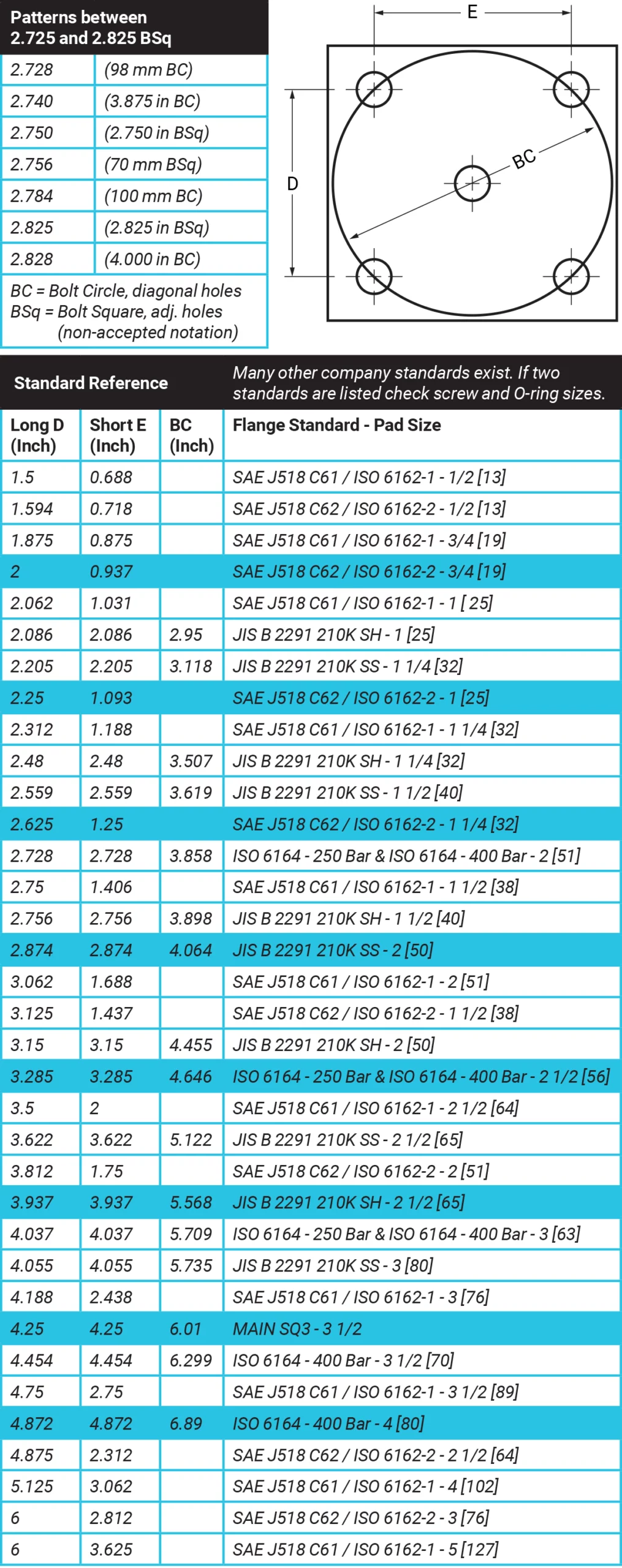
BC stands for bolt circle, which is the distance between the centerlines of diagonal holes. If D = E, the distance between adjacent holes, that value defines a “bolt square”. The table (right) shows the seven common patterns between 2.728 inches bolt square and 2.828 inches bolt square. The numbers in parenthesis show the scheme and common number for the pattern.
It is trickier to determine the standard related to a square pattern. A square bolt pattern can be based on a bolt circle or what can be called a bolt square. Generally, people use whole numbers or common fractions when designing parts. A four-bolt pattern could have common numbers between adjacent screws (bolt square), or diagonal screws (bolt circle). It gets further complicated by having inch and metric numbers. Further help can be derived from knowing where the equipment is from and who manufactured it. Germany and other European countries generally use a bolt circle while the Japanese use a bolt square and both are, of course, metric. Square inch patterns are used by some US manufacturers including Vickers, Oilgear, and others. MAIN’s website offers a “mounting pattern to flange standard” chart of the SAE, JIS, DIS, and ISO patterns.2
2. Screw size and type (inch/metric)
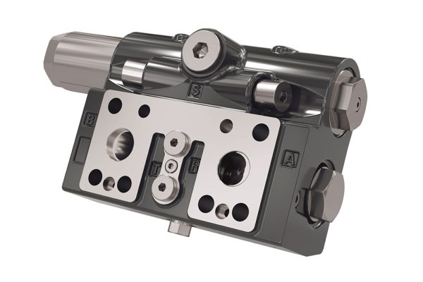
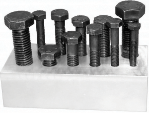 The standard will also let you know the size of the screws. You may need to determine if the tapped holes are inch or metric. The SAE/ISO standards allow both, and many of the US branches of foreign companies design equipment using a “metric” pattern but substituting inch screws.The SAE/ISO pattern allows a common clearance screw hole for most sizes but tap holes are still different. Be careful to make sure that the correct screw is being used. The photo shows that mismatches are possible.In the back row of the figure to the side, metric screws 45mm (1.77 inches) long are put into inch-size tapped holes and the front row has 1.75-inch screws (44.45 mm) long are put into metric tapped holes. The difference in lead and diameter allows some combinations to go very deep and become tighter (due to pitch variations) parts together. The engagement of the screw can be very small as well, which results in thread stripping among other problems.The screw material grade is generally 10.9 or 12.9 metric grades or Grade 8 and ASME B18.3 inch grades. It should be noted that ISO 6164 specifies special installation instructions for installing screws.
3. O-ring size
The last item that the standard gives you is the O-ring size for the pattern. Most current standards use the O-ring as a crush seal, with the O-ring groove fill approaching 95% or higher in worst-case scenarios. The O-ring diameter is important for determining the MRWP as well as the maximum fluid passage. The O-ring material is determined by the hydraulic fluid, the temperatures, and cost. In the past, the O-ring hardness was 70 durometer but current specifications call for a harder 90 durometer. The 70-durometer O-ring is softer and fills in scratches and voids better while the harder 90-durometer O-ring resists extrusion better.
All of the above is given by the standard and having the standard saves users from having to figure it out and the mistakes that may result.
4. Maximum rated working pressure (MRWP)
The maximum rated working pressure of the flange connection is generally determined by the size and strength of the screws, the area within the O-ring diameter, and the design factor. The design factor can vary from about two to four or more, with four generally being used for standard commercial work. Generally making the flange thicker will not increase the MRWP. As pressures and sizes increase, this design factor’s value has been brought into question.
MAIN has seen various users and designers do some interesting things that have a dynamic effect on the MRWP. The first is to turn the bolt holes into slots to solve adjustments or other issues. This could be useful, but the MRWP can drop 50% or more and fatigue life may be affected. The area under the screw head is of vital importance to the holding power of the pad.
Another idea is to eliminate one screw hole to allow an elbow to be made without reducing the flow. At first thought it would seem that the MRWP is reduced by 25% (1 of 4 screws) but it actually reduces by up to 33% or more because the force of the screws does not align with the pressure force under the O-ring, resulting in bending moments.
The pressures that the flange is rated for are determined from above. It is useful to know the pressure the flange will see, including spikes and intensified pressures caused by a cylinder in the hydraulic circuit, both of which can sometimes be above system pressure. This will determine if changes need to be made.
5. Flange type (O-ring or flat-faced)
The component flange pad attached to will determine the flange type. A hydraulic flange union is made between a flat-faced component and a component with an O-ring. In general, the O-ring component has clearance bolt holes, and the flat-faced side has tapped bolt holes. If both the component and the flange have O-rings or both are flat-faced, a gender changer is needed. Gender changers are flat-faced/flat-faced or O-ring/O-ring components that are sandwiched between the other components to provide the missing surfaces.
6. Connection type
Connection type is where things become interesting as there are many choices. Connection type refers to the connections on the other end(s) from the flange pad. They can be: threaded (NPTF, SAE Straight thread, BSPP, BSPT, ISO 6149, and more); welded (butt weld, socket weld, j groove, for pipe or tube in inch or metric sizes); brazed (solder, silver solder, copper solder); flanged (SAE J518/ISO 6162, ISO 6164, ANSI B13.3, MAIN-SQ6000, MAIN-SQ3000, or other); and blind. Blind flanges are used to seal off future expansion points. Other cases involve a socket weld flange on one side and a straight thread flange on the other. As long as the flanges have the same mounting pad and different flange types, there is no problem forming a connection.
7. Connection size
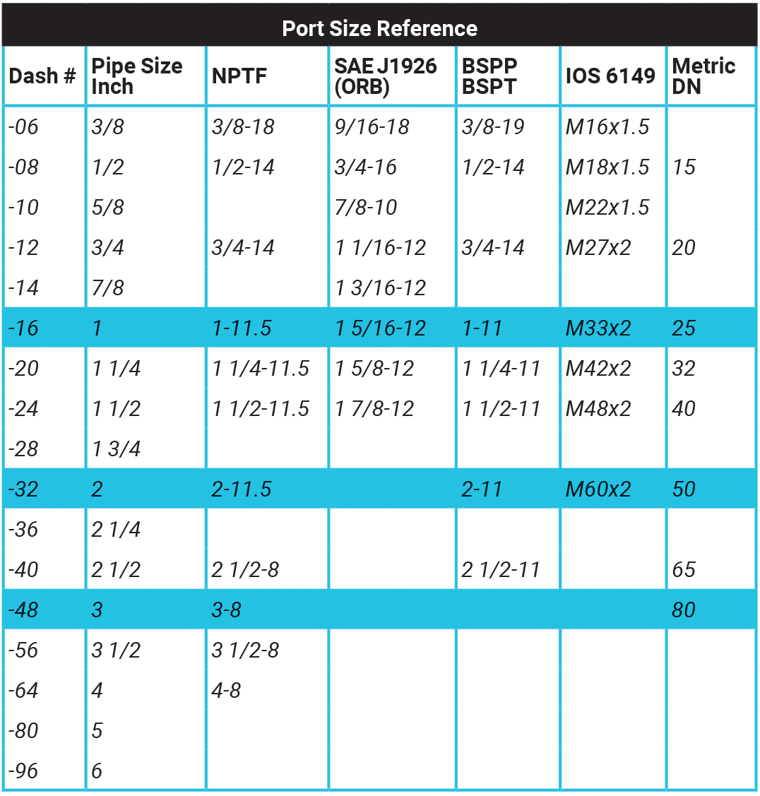
The connection size refers to the size of the fitting that the flange is adapting to. The flange may be a flange head to a hose that is already been attached but at other times the flange will be adapting to another fitting, pipe, or tube. Reducers are readily available. Connection sizes are also referenced by DN or Dash numbers. The Port Size Reference chart shows typical sizes and threads. Remember that pipe size is based on the approximate ID while tubes are based on the approximate OD.
8. Geometry
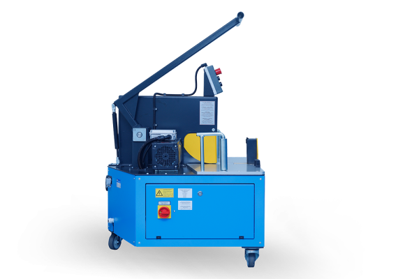
Geometry, or the shape, is generally easy to determine and describe. There are in-line, elbow, tee (both run and branch), Y, and cross. MAIN uses the O-ring face or the largest flat-face, as the starting point of its numbering system. On a tee, if there is a port opposite the O-ring face (referred to as “on the run”), the connector is a run tee. If the O-ring face is 90° from the port face (referred to as “on the branch”), it is a branch tee. A side outlet elbow has three connection ends that are 90° from each other. If a connector has an asymmetric shape, it may have a hand, and it might be necessary to describe it in terms of “right hand” or “left hand”. For example, if the asymmetric feature points left, it is described as having a “left hand”. Putting this together is a central hydraulic testing center with multiple test stands.
A central hydraulic power center and a supply line and discharge line around the outside with spots for future expansion are installed. This involves having three to six-inch flange-size high-pressure lines running around the perimeter joined with branch tees. The run of the tees is three to six-inch size ISO 6164, MAIN’s 3000 series, or MAIN’s 6000 series flange pads and one to two-inch SAE J518 flange pads (or any other port) branch on top to supply each station.
9. Material
Many materials are available. MAIN offers flanges made from AISI 1018 CF, ASTM A516-70 PVQ, AISI 1117, and AISI 1020 as stock items and can turn around any commercially available material quickly. Most of our AISI 1018 and AISI 1117 materials are bought from the mill to MAIN’s special requirements. This allows for improved material traceability and certification.
Stainless steel flanges are stocked by many suppliers in 304L grade and 316L grade as well. The “L” in stainless grades stands for extra low carbon and aids in welding. Welding non “L” grades can result in an area that is not stainless steel in the heat-affected zone and will rust. Other options such as aluminum, nickel, cuprous-nickel, and any commercially available material are available quickly. Some installations might require the use of specific materials to meet applicable codes. Know these codes and who will inspect and approve the part; sometimes one agency is required to inspect another’s code with conflicting requirements.
10. Extras
Other options available include counterbored bolt holes, offset ports, mounting holes, “chopped blocks”, and gauge/sampling ports. The flange is one of the least expensive locations for a gauge or sampling port.
Mounting Kits
Screws-size & type (inch/metric and socket/hex)
To mount the O-ring flange to the pad, a mounting kit consisting of 4 screws, 4 washers, and an O-ring is used. Unlike ANSI and API flanges, hydraulic flanges generally join metal to metal without a flat gasket between the surfaces; sealing is achieved by employing an O-ring that is compressed in a groove. This reduces fatigue issues and allows full torque to be applied to the bolts. High-strength fasteners are generally used (SAE grade 8 hex head, ANSI B18.3 socket head, ISO grade 10.9 hex head or socket head or better). The screw size is determined by the tapped holes and normally has a coarse thread.
The use of corrosion-resistant bolts presents separate issues. In general, what makes bolts stronger also makes bolts less corrosion-resistant. Finding 10.9 metric grade bolts in stainless steel might not be possible, and they can be quite expensive. The SAE standard for Grade 8 screws specifies a material other than stainless steel. Bolts made from a corrosion-resistant material might not be able to match both the tensile strength and yield strengths of the bolts specified in the relevant flange standard, so application-specific accommodations have to be made.
O-Ring
Most hydraulic flanges use an O-ring for sealing. Many different materials and some different designs are available but the most common material used is Buna “N”. The material to be used is determined by the temperature and the fluid. The hydraulic fluid supplier should be consulted for the appropriate O-ring material.
In addition to material and size, O-rings are specified by hardness (durometer). For many years 70 durometer O-rings were used, but in the last 20 years or more 90 durometer O-rings have been used. If a SAE J518 flange is being used within specifications, it is many people’s opinion that it should not make a difference.
Conclusion
While selecting the right flange can seem like a daunting task, we hope that this article has provided you with the necessary steps to understand and begin a conversation with an engineer which will be quicker and more productive than you would have originally. We hope that this paper will reduce the number of issues users see and make it easier to order the correct flange the first time, replace an old flange or just gain more knowledge about flanges.
1 https://www.mainmanufacturing.com/pdf/measure.pdf
2 https://www.mainmanufacturing.com/RF_Series.aspx
Share this information.
Related Posts


Sponsor

Sponsors