Understanding the Function of Accumulators
Accumulators come in a variety of forms and have important functions in many hydraulic circuits. They are used to store or absorb hydraulic energy.
When storing energy, they receive pressurized hydraulic fluid for later use. Sometimes accumulator flow is added to pump flow to speed up a process. Other times the stored energy is kept in reserve until it is needed and may be independent of pump flow. This could be for emergency power when pump flow is not available. It could be used to hold pressure in a system when pump flow has stopped by providing fluid to compensate for leakage.
There are several ways in which accumulators are used to absorb energy. The returning flow from a large-bore cylinder may be greater than should be conducted by the plumbing. A low-pressure accumulator can receive a portion of the flow and then discharge it at an appropriate rate for the plumbing. Hydraulic fluid has a relatively high rate of thermal expansion. If a volume of fluid is confined and unable to expand or contract due to temperature changes, there could be very high pressure that could damage equipment or low pressure that could cause air bubbles in the hydraulic fluid. Accumulators can be used to absorb the expanding fluid and/or supply the contracting fluid. They also absorb and dissipate energy when used to dampen pressure pulses, reducing noise and vibration.
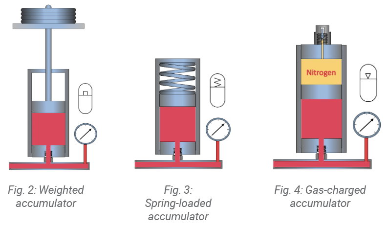
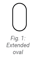 Accumulators are preloaded so that there will be a minimum pressure for any available fluid. The three types of preloading are weights, springs, and gas. The symbol for a fluid energy storage or absorption device is the extended oval shown in figure 1. The specific type of accumulator is shown by the additional symbols within the oval, as shown in figures 2, 3, and 4. Of the three types of accumulators, only the weighted one has constant pressure. The pressure is produced by the weight divided by the area of the supporting piston. Weighted accumulators are appealing from the perspective of circuit design but are not usually practical for mobile applications. They must be mounted vertically, they are relatively large, and they are heavy. Spring-loaded and gas-charged accumulators weigh less, take up less space, and can be mounted horizontally, although it is preferred to mount accumulators vertically.
Gas accumulators are sometimes referred to as having a gas spring. In the gas accumulator category, there are six main types:
- Piston
- Noise suppressor
- Bellows
- Diaphragm
- Bladder
- Air-over-oil
Like a compressed spring that wants to push toward its extended position, a compressed gas wants to push toward its decompressed state. The gas used is incombustible, usually nitrogen, unless the pressure is very low. Even though there is usually a separating element between the gas being used and the hydraulic fluid, using a gas that contains oxygen, such as air, can result in an explosion. As the air is compressed, it is heated, and if the heated oxygen interacts with the hydraulic fluid, it may cause ignition.
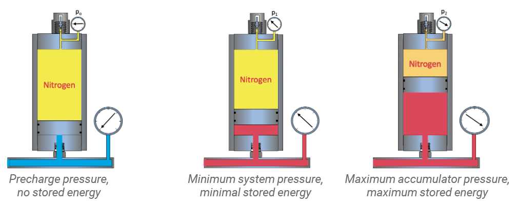
A hydraulic mechanic may be required to check the gas pressure in an accumulator. Three different pressures are considered when working with gas-charged accumulators. These pressures are not always described in the literature and may simply have the designation of p0, p1, and p2.
p0 = Precharge pressure: The original gas pressure before any hydraulic fluid is stored in the accumulator.
p1 = Minimum pressure: The lowest hydraulic pressure requirement of the system.
p2 = Maximum pressure. The highest pressure that the accumulator will see.
Each of these pressures provides information about the hydraulic system. If the accumulator is fully charged (is holding the maximum amount of hydraulic fluid), the maximum system pressure reading is p2. If this reading is too high or too low, the controlling relief valve or pressure compensator may need to be adjusted. During operation, the minimum system pressure (p1) should be noted. Then the precharge (p0) is tested to be sure it is at the specified pressure below p1. Over time, some of the gas may escape, reducing the precharge. If this happens too frequently, it indicates that the barrier has failed, and the accumulator must be repaired or replaced. When an accumulator loses its precharge, it will no longer store energy. The accumulator can be filled to full system pressure, but there would be no energy stored in the gas spring to push the fluid out.
Sizing gas accumulators: Gas accumulators are not described by how much hydraulic fluid they can hold. They are described by the volume of gas they hold. A 1-liter accumulator will hold 1 liter of compressed gas. As hydraulic fluid enters the accumulator, it compresses the gas, increasing its pressure and reducing its volume. The amount of stored hydraulic fluid is the difference between the original gas volume and the new compressed volume. A 1-liter gas accumulator half-filled with hydraulic fluid would have ½ liter of compressed gas and ½ liter of stored hydraulic fluid.
Piston accumulators: These are made of cylinders with pistons. The seals on the pistons are the separation elements that isolate the gas from the liquid. Like all gas accumulators, they are precharged (p0) at a pressure that is below the minimum hydraulic pressure (p1). This is so that hydraulic pressure will always prevent the piston from bottoming out.
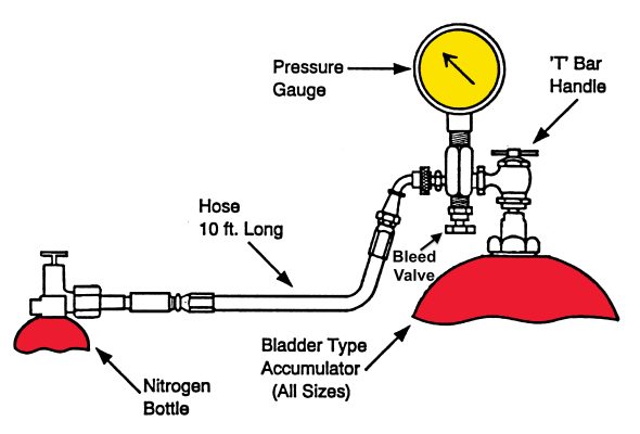
Bladder accumulators: A metal or composite bottle is fitted with an expandable bladder used to store pressurized gas and keep it separated from the hydraulic fluid. A charging valve is connected to the bladder at the top of the bottle. At the bottom of the bottle, there is a spring-loaded poppet valve that is in the open position. When the bladder is precharged (p0), it stretches and completely fills the bottle, closing the poppet. The poppet prevents the bladder from being destroyed by extruding into the piping.
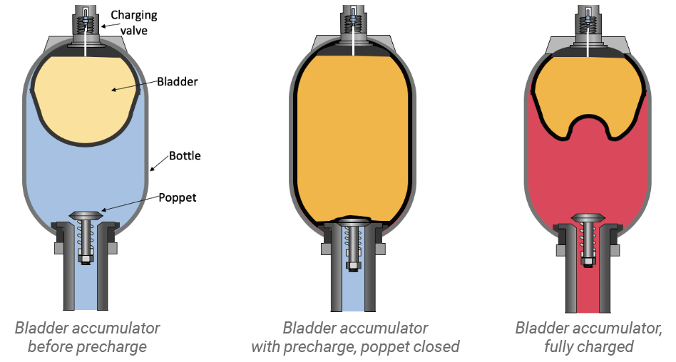
When the accumulator is filled with the maximum volume of hydraulic fluid, the gas is compressed to the maximum pressure (p2). Just as in the piston accumulator, the precharge is lower than the minimum system pressure. In this way, the bladder does not bottom out against the poppet. If the precharge is too high, the bladder may extrude under the poppet and be pinched and torn as the poppet closes.
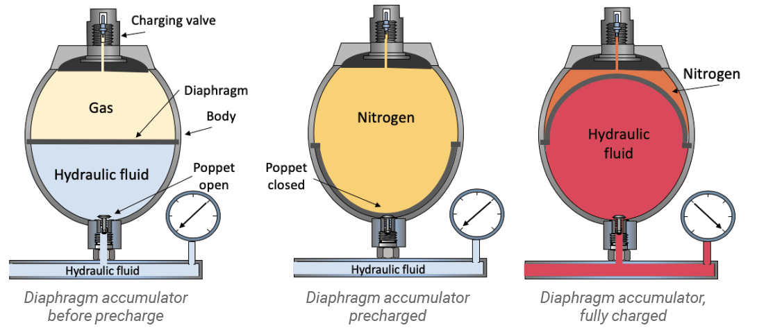
Diaphragm accumulators: Diaphragm accumulators use a rubber disc to isolate the gas from the liquid. This disc is positioned between two spherical shells that are either welded or screwed together. The compartment above the diaphragm is filled with nitrogen. The compartment below is directly connected to the hydraulic circuit. There is a poppet that prevents the diaphragm from extruding into the piping. Some of the diaphragm accumulators are not serviceable so that if the disc ruptures or the precharge is lost, they must be replaced.
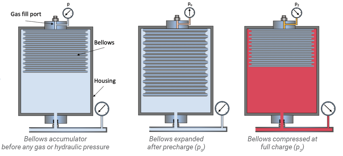
Bellows accumulator: A less common accumulator is the bellows type. It consists of an expandable metal chamber inside a housing. The metal chamber is precharged with nitrogen, and the housing is then exposed to the high-pressure hydraulic fluid. The walls of the expandable container do not touch the walls of the housing, therefore there is no frictional wear as the bellows expand and retract. They do not use elastomeric bladders, diaphragms, or piston seals; therefore they are not subject to the limitations of elastomers. Metal bellows operate reliably in high temperature, extremely abrasive, and harsh environments. The welded bellows are hermetically sealed and can operate reliably without servicing or maintenance.
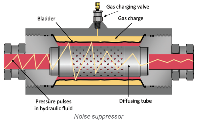
Noise suppressor: Most hydraulic pumps produce energy pulses as the individual chambers discharge fluid. These energy pulses produce vibration and noise. A type of accumulator is used to dampen sound and reduce vibration in hydraulic lines. It is an inline device equipped with a bladder that surrounds a diffusing tube. The bladder is charged with gas, typically at ½ the hydraulic system pressure. As the fluid passes through the suppressor, much of the energy pulse is absorbed, providing reduced vibration and noise.
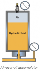 Air-over-oil: An air-over-oil system is a simple version of an accumulator. However, it has some serious limitations. It must be mounted vertically and be a relatively low-pressure system. High-pressure air can become very hot and could cause ignition of the hydraulic fluid. As seen in the illustration, the hydraulic pressure will be the same as the air pressure. Because there is no barrier between the air and the hydraulic fluid, the unit should not be subject to a lot of motion. Movement and vibration may cause a mixing of the air with the hydraulic fluid, producing a sponginess in the system.
Test Your Skills
1. Accumulators are used to:
a. compress nitrogen.
b. compress hydraulic fluid.
c. accumulate particulates.
d. store or absorb energy.
e. reduce flow.
2. The advantage of the weighted accumulator is that:
a. it can be mounted horizontally.
b. it is lighter in weight.
c. it takes up less space.
d. it can be charged with shop air.
e. it has a constant pressure.
See the Solutions
1.d, 2.e
The material in this article is included in the upgraded Mobile Hydraulic Mechanic Certification Study Manual to be released in 2021.
Share this information.
Related Posts
The Effects of Pressure Compensated Components on Control Systems

Test Your Skills: Stopping & Holding Loads Safely

Test Your Skills: Ensure Component Compatibility

Stopping a Load with a Shock Absorber
Understand the Function of Hydraulic Components in Circuits: The Application of Pumps and Intensifiers
Gas-Charged Hydraulic Accumulators
2 thoughts on “Understanding the Function of Accumulators”
Leave a Reply
Sponsor

Sponsors
We required diaphragm accumulator. Bladder accumulator and piston type accumulator.
Hydraulic accumulator use in multiple industry. Oil gas, Fertilizer, Paper, sugar, automobile industry, textiles, and etc.
Looking to use a Piston Spring Accumulator Around %00 Psi. to Return Hydraulic Fluid During Pressure Drops after the External Relief Valve Instantly Closes, also Suggested Flow Paths on Plumbing any Information would Be Appreciated Thanks