Understand the Function of Hydraulic Components in Circuits: The Application of Pumps and Intensifiers
Pumps
A pump is a device where there is a mechanism for increasing and then decreasing the size of a volume chamber by means of rotary and/or reciprocating linear movement.
Positive and non-positive displacement: A positive displacement pump is one where the spaces between the moving parts are quite small and so there is little difference in pump output over the rated pressure range.
A non-positive displacement pump has relatively large clearances between the moving parts and therefore a diminishing output as the resistive pressure rises. The majority of hydraulic pumps are positive displacement. Centrifugal pumps would be examples of non-positive displacement pumps.
Fixed displacement: A fixed displacement pump is a device where the geometric displacement does not change. This means that as the rpm of the pump increases, there will be a corresponding linear change in the pump output. A pump that pushes 10 liters per minute (2.6 gpm) at 1,000 rpm will produce nearly 20 liters per minute (5.2 gpm) at 2,000 rpm. Resistive pressure will impact the pump output depending on the relative efficiency of the pump. Many pumps are rated by their theoretical displacement which does not account for internal leakage. Leakage needs to be considered when sizing a pump.
Variable displacement: A variable displacement pump has a positive displacement but has volume chambers that can change size. This is common in vane and piston pumps but is rarely found in gear pumps. The advantage of the variable displacement pump is that it allows the designer to provide greater flexibility and efficiency within a system.
Pump Controls
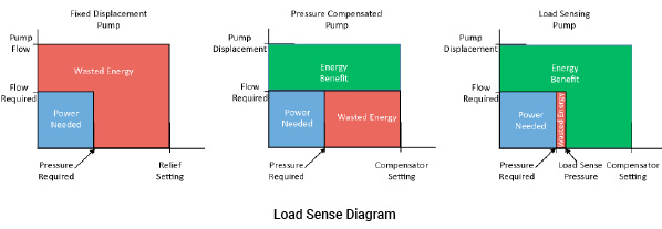
Pressure compensation: One of the most common types of pump control for the variable displacement pump is pressure compensation. This control limits the pressure in the system and at the same time limits the flow to the system requirements. The result is to reduce the energy that would be lost when excess fluid is dumped across a relief valve.
Load Sensing: Load sensing is another popular type of variable displacement pump control. Sometimes referred to as pressure and flow control, it responds very much like pressure compensation and is always found in parallel with a pressure compensator control. The difference is that the load sensing is done using a relatively light spring, from 14 to 28 bar (200 to 400 psi). A sensing line that reaches beyond a flow control valve (it may be a directional control valve) exposes the spring chamber to the load pressure. The result is a setting of load induced pressure plus spring pressure. In other words, the pressure setting will be 14 to 28 bar higher than any load induced pressure. To prevent over pressurization, there is a pressure compensator in parallel with the load sensing compensator. Load sensing control is especially useful when there is a single function being controlled with variable speed and/or pressure.
Torque limiting: A system may require a high flow or a high pressure, but not need both at the same time. The torque limiting control (sometimes referred to as power limiting) is a third control function, added to pressure compensation, that responds to the combined flow and pressure to reduce the pump displacement so that the input torque will not exceed the ability of the prime mover.
Intensifier and Flow Augmenter
Sometimes a system may demand low flow/ high pressure or high flow/low pressure. Pressure intensifiers and flow augmenters are available for this purpose. There are two types of intensifier/augmenters.
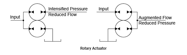
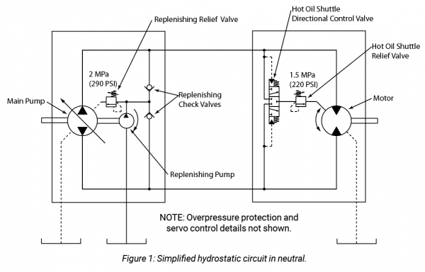
Displacement type: The device consists of two or more hydraulic motors mechanically linked. As a pressure intensifier, flow enters all the motors but some of the motors discharge their flow to the reservoir. The result is a pressure intensification at the outlet of the motor whose discharge is directed to the load. The level of intensification is the ratio of the total displacement of the motors divided by the displacement of the motor whose discharge is directed to the load, as in the following equation.
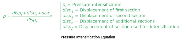
For example, two motors, each with a displacement of 16.4 cc (1 in3), are mechanically linked. The discharge of one motor is directed to the reservoir and the other to the load.
pi = (16.4 cc + 16.4 cc) / 16.4 cc = 32.8 cc / 16.4 cc = 2
pi = (1 in3+ 1 in3) / 1 in3 = 2 in3/ 1 in3 = 2
An input pressure of 105 bar (1,500 psi), intensified by 2, would provide an output pressure of 210 bar (3,000 psi). However, the working flow would be half that of the input flow. Power in must equal power out. The intensified pressure is limited to the pressure rating of the motors.
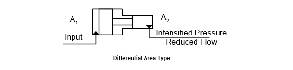
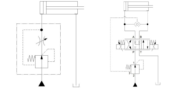
Differential area type: These are best suited for higher pressures and when a momentary condition is required. The device consists of two mechanically linked pistons with different areas. The amount of pressure intensification is the ratio of the areas of the two pistons: A1 ÷ A2. If A1 = 10 units and A2 = 2 units, the ratio will be 10 ÷ 2 = 5. An input pressure of 140 bar (2,030 psi) will provide an output of 700 bar (10,150 psi). The illustration below shows the input pressure from a hydraulic source. It is also common for compressed air to provide the input pressure. As can be seen in the illustration, there will only be flow and intensified pressure until the pistons reach the end of stroke. A circuit can be arranged so that there is a reciprocating motion of the pistons to provide continuing flow and pressure.
Test Your Skills
1. A positive displacement pump:
a. Is the same as a fixed displacement pump.
b. Reduces flow as RPM increases.
c. Has only a small change in flow as pressure increases.
d. Has a large change in flow as pressure increases.
e. Has large spaces between the moving parts.
2. A variable displacement pump:
a. Is a positive displacement device.
b. Must have a minimum and maximum volume control.
c. Must have a fixed RPM.
d. Is usually a gear pump.
e. Cannot be a vane pump.
3. The main relief valve in the figure shown below is set at 200 bar. Cylinder 1 has no load while extending and cylinder 2 requires 120 bar to extend. What would be the pressure reading at the inlet of the 50/50 flow divider while the cylinders extend?
a. 60 bar.
b. 100 bar.
c. 120 bar.
d. 300 bar.
e. 400 bar.
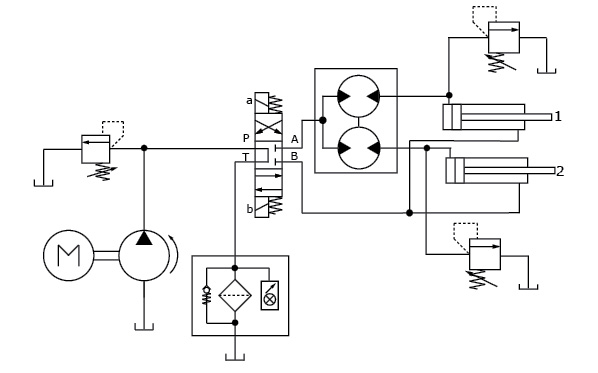
4. The main relief valve in the figure above is set at 200 bar. What is the maximum pressure that could be seen at the outlet of the flow divider?
a. 60 bar.
b. 100 bar.
c. 120 bar.
d. 300 bar.
e. 400 bar.
See the Solutions
1.c, 2.a, 3.a, 4.e.
Share this information.
Related Posts
Sponsor

Sponsors