Vacuum Cup Holders
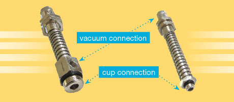
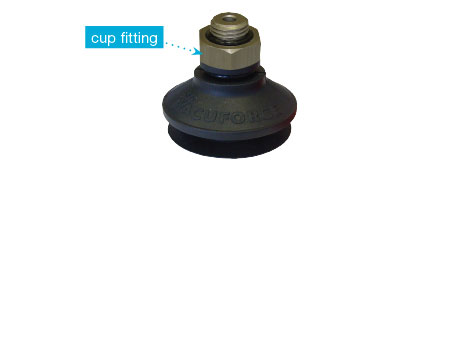
Vacuum cups are often mounted directly to machinery via a cup fitting as shown in the cup assembly in Fig. 1. This cup fitting will screw into the machinery lifting arms or handling device. If only one cup is being used or a pair to pick up cardboard sheets on a carton-erecting machine, for example, this method would normally prove adequate. However, when handling very large sheets or objects such as wooden panels, sheets of glass, or marble slabs, level compensators as shown in Fig. 2 would be more appropriate and certainly offer better compliance for the machine builder and ultimately the machine user.
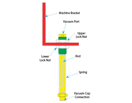
Level compensators consist of a vacuum cup connection thread or barb (for smaller cups) and a threaded vacuum port both positioned in a common solid metal rod. This rod diameter is assembled through a bushing with a spring surrounding its outside diameter (sometimes this spring is internal). The bushing is placed through a machine bracket, and lock nuts are tightened to secure it as shown in Fig. 3. The upper lock nut is used to determine the height of the level compensator once it is mounted through the machine bracket, and the lower lock nut is used to secure the holder in position.
Level compensators or spring cup holders are installed to enable automated machinery to have an approximate approach height to the part being handled. They also enable the handling of surfaces that are not perfectly square to the machine approach or are not flat, such as a concave or convex surface.
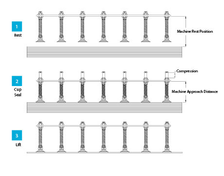
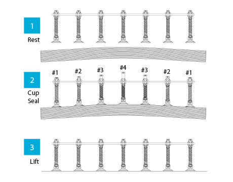
Fig. 4 demonstrates the approximate approach feature. In the machine REST position, all level compensators are at the same height and under spring tension. As the lift frame of the machine approaches, the cups make contact with the load to be lifted (CUP SEAL). The machinery can continue past this point of cup contact to ensure that the cups make firm contact by the compression distance shown. The benefit of using level compensators in this application is that the approach distance can be approximate each time the machine “de-stacks” further layers. If the full stack height of the parts is higher than the stroke of the level compensators, periodically the machine will adjust the height offset.
If holders were not used in this application and the cup was “hard mounted” to the machinery via a simple cup fitting as shown in Fig. 1, the machine approach distance would have to be very accurate to ensure contact was made by the vacuum cups, and this distance would change for every layer pick. This could be overcome by the use of a bellows-type cup, which offers its own “compensation,” but this is limited by cup compression distance of maybe only half an inch or so depending on the cup design. The level compensators offer the user and machine operator a very easy machine set up.
Fig. 5 demonstrates how cup holders can be used to pick up a convex surface. As the machinery approaches, cup holder #4 makes initial contact and seals. As the machine continues downwards onto the load cup holders, #3, #2, and #1 make contact in that order with cup holder #4 having the most compression, and consequently, the holder rod protrudes the most through the holder bushing.
As the machine returns vertically upwards in the LIFT part of the cycle, all cup holders return to the REST position. This method of cup-holder application also allows for the sealing against concave or angled layers.
The difference in height between the highest and lowest points of the workpiece will determine the type of holder to be used in respect to its compression distance.
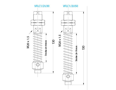
Fig. 6 shows two catalogue drawings of identical holders but with different compression distances. The part number of this type of product typically reflects the compression distance as shown in the Fig. 6 illustration. The model on the left has 30 mm of compression, whereas the model on the right has 50 mm—the same fundamental holder but with a different compression distance.
Cup holders are ideal for handling large flat or slightly curved surfaces, but cup holders should not be used in a horizontal position unless the load being handled is very lightweight. The manufacturer should be able to offer this load data. As a rule, however, the user will experience higher wear than usual between the rod and the bushing of the holder if it is being used in a horizontal or shear motion.
This article is intended as a general guide and as with any industrial application involving machinery choice, independent professional advice should be sought to ensure correct selection and installation.
Daniel Pascoe is General Manager of Vacuforce Inc, manufacturer and distributor of vacuum components and systems for industry in North America. Daniel can be reached via the Vacuforce website at www.vacuforce.com, or directly at dpascoe@vacuforce.com. Find Vacuforce on Facebook and keep up to date on Twitter.

