Vacuum Level & Volumetric Flow Rate
The following is an opinion article written by Dane Spivak of Davasol Incorporated, an industrial brand management firm with many clients, one of which is Vacuforce LLC, based in Indianapolis, Indiana. Vacuforce partnered in writing this article. The example numbers enclosed have been arbitrarily chosen and do not reflect real-life situations. Contact Dane Spivak at dspivak@davasol.com.
Industrial parts manufacturers provide performance data for components to offer the user an understanding of its capabilities. At times there can be a laundry list of specifications, so it is important to identify which criteria impact the output of the system to ensure a good fit. In vacuum, the vacuum level and volumetric flow rate are the two key factors.
VACUUM STATE
Before we discuss vacuum performance, we must first understand the state of vacuum. Vacuum is a pressure lower than atmospheric pressure in a known volume. There are a few key takeaways from this definition. First, vacuum is a pressure that can be measured in common compressed air units such as psi, bar, or kPa. However, there are pressure measurements specific to vacuum; these will be discussed later in the article. Second, vacuum pressure is lower than atmospheric. This is important because atmospheric pressure controls the datum point of vacuum as well as the available pressure the vacuum has to offer. Finally, a defined known volume is used to determine a vacuum state. This does not mean it has to be a closed system but rather a specific space in which vacuum can be considered and measured.
 VACUUM LEVEL
Vacuum level is essentially a synonym for vacuum pressure. Vacuum level refers to the numerical measurement of vacuum pressure in a system using a unit of measurement scale. Vacuum levels quantify how much lower the pressure is than the atmospheric pressure and, in some instances, how close the pressure is to absolute pressure (zero). Absolute pressure is reached when every particle of gas (air) and other pressure substances are removed from a volume. This is where the term “in a vacuum” comes from in physics when theorizing with zero air resistance.
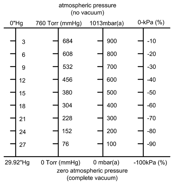
Let’s talk numbers. Our definition of vacuum states that atmospheric pressure is the datum point. Earth’s atmospheric pressure is the pressure exerted by the “weight” of the air in the atmosphere. Although atmospheric pressure changes with factors such as altitude, weather, and geographic location, the mean value is approximately 14.7psi at sea level. We can convert 14.7psi to units of measurement that are all equal in absolute value: 29.92”Hg, 760Torr (mmHg), 1013mbar, 101.3kPa.
Figure 1 compares vacuum measurement scales. Note that the “Hg and kPa(%) are differential scales that start at zero, which is actually atmospheric pressure, whereas the Torr and mbar(a) peak at atmospheric pressure and reach zero at absolute pressure. The scale of “Hg is useful for applications in which the pressure differential is important, such as vacuum cup gripping. The vacuum pressure difference from atmospheric pressure determines the gripping force of the cups. On the other hand, the Torr scale is a more appropriate measurement in vacuum sealing for food packaging applications , where the importance is understanding how much air is remaining in the system instead of how much was removed. Both scales measure vacuum though the datum points are different. It is necessary to have both scales for accuracy because atmospheric pressure is inconsistent and always changing.
The most common tool to measure vacuum levels are gauges, which often use “Hg units, though -kPa and mbar(a) are popular as well. Digital sensors are also used, usually when vacuum is tied into other automation or PLC needs.
 VOLUMETRIC FLOW RATE
Volumetric flow rate, often referred to simply as flow, is the volume of fluid that passes per unit of time. Vacuum flow determines the volume of air that can be moved over time, which translates to how quickly air can be suctioned. Common units of measurement for flow rates include cubic feet per minute (CFM), liters per minute, and gallons per minute, to name a few. There are many more, but unlike vacuum levels, flow units can be interchanged by their associated multipliers, similar to millimeters, inches, feet, meters, and so forth.
Understanding flow ratings and pump curves is important in predicting system performance. Most often, manufacturers provide a single flow rating for vacuum generation units. If we consider the flow units of CFM, generally the published numerical value from a manufacturer is the standard cubic feet per minute (SCFM) rating of the pump, which is also the maximum amount of flow the pump can produce. The SCFM rating of the vacuum pump refers to full open flow at room temperature and atmospheric pressure (zero vacuum). However, the pump SCFM rating is usually not what the vacuum system truly experiences because the conditions change at the point of use for many vacuum systems. Flow ratings that are not encompassed by standard conditions are described as actual cubic feet per minute (ACFM). This is where the pump curves are introduced for a clearer interpretation of how well a pump will function under ACFM or non-standard full flow conditions.
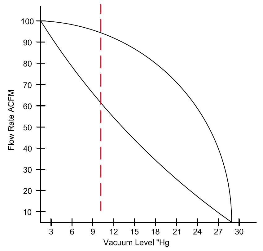
Figure 2 measures the vacuum level and flow of two pump curves. One pump curve maintains higher ACFM than the other and therefore offers higher actual flow capacity. Although both pumps have the same SCFM ratings, this graph demonstrates different ACFM ratings at various vacuum levels. The ACFM ratings can be crucial in many applications. If a system requires a minimum of 80CFM at 10”Hg, it may sound like a 100SCFM pump would be adequate. However, as we learned from Figure 2, the ACFM rating may be less than 80CFM at 10”Hg, as demonstrated by the red vertical line. Pump performance curves are usually available from the manufacturer and should be studied if flow is a contributing factor as the vacuum level increases.
Measuring devices such as flow meters can be used to determine flow ratings in a system. The latest models use digital readouts, though simplified dial reads are available too. It is important to note that the standard and actual CFM unit ratings were used as an example. The same concept applies to all other units of volumetric flow rates.
 FLOW 7 VACUUM LEVEL RELATIONSHIP
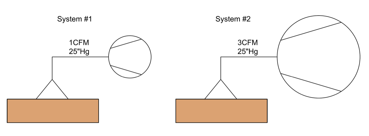
Figure 2 shows that flow and vacuum level share a relationship. Let’s use real-life examples to visualize and better understand how the two affect each other. Figure 3 shows two identical systems of a vacuum pump connected to a vacuum cup sealing against a smooth flat surface. We can consider this a closed system because the vacuum cup provides a “perfect” seal against the product surface. System 2 uses a 3CFM vacuum pump while system 1 generates 1CFM, but both pumps have an equal maximum vacuum level of 25”Hg. We will consider both pump types to be the same, so their performance curves are comparable in pattern. Because these are closed systems, both pumps will reach their maximum vacuum levels of 25”Hg. However, since system 2 provides more flow, the evacuation time to reach 25”Hg will be faster than system 1. That said, if the goal is to reach 25”Hg, both pumps will be successful. If the 1CFM pump does not reach 25”Hg fast enough, the 3CFM pump would be a better fit. But a pump offering more than 3CFM would be needed if it does not reach its desired vacuum level in a timely manner.
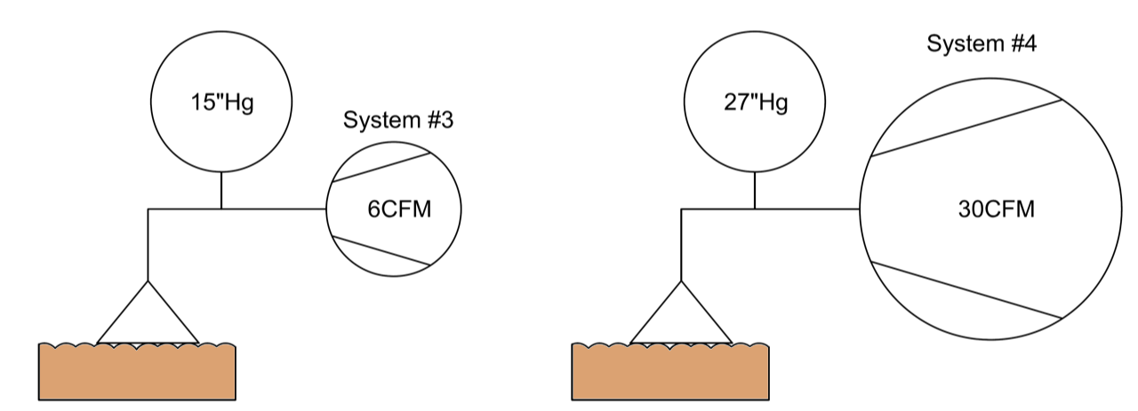
For our next example, let’s consider systems similar to figure 3, but instead the vacuum cups are sealing against an uneven rippled surface, such as corrugated cardboard. We will refer to these as system 3 and system 4 shown in Figure 4. We can no longer consider this a closed system because the cups are not creating a “perfect” seal against the surface, and therefore air is bleeding into the vacuum system. This is commonly known as air/vacuum leakage. Since system 4 generates more flow, it is capable of compensating for more leakage compared to system 3. The higher flowing vacuum pump is removing more air at a faster rate, so it can better overcome the leakage of air bleeding into the system through the imperfect seal of the cups. This results in a higher final vacuum level in system 4.
Depending on the system design, it is possible that a pump may not have enough flow to overcome leakage. In that case, selecting a larger flowing pump to overcome the leakage flow would help generate a vacuum level.
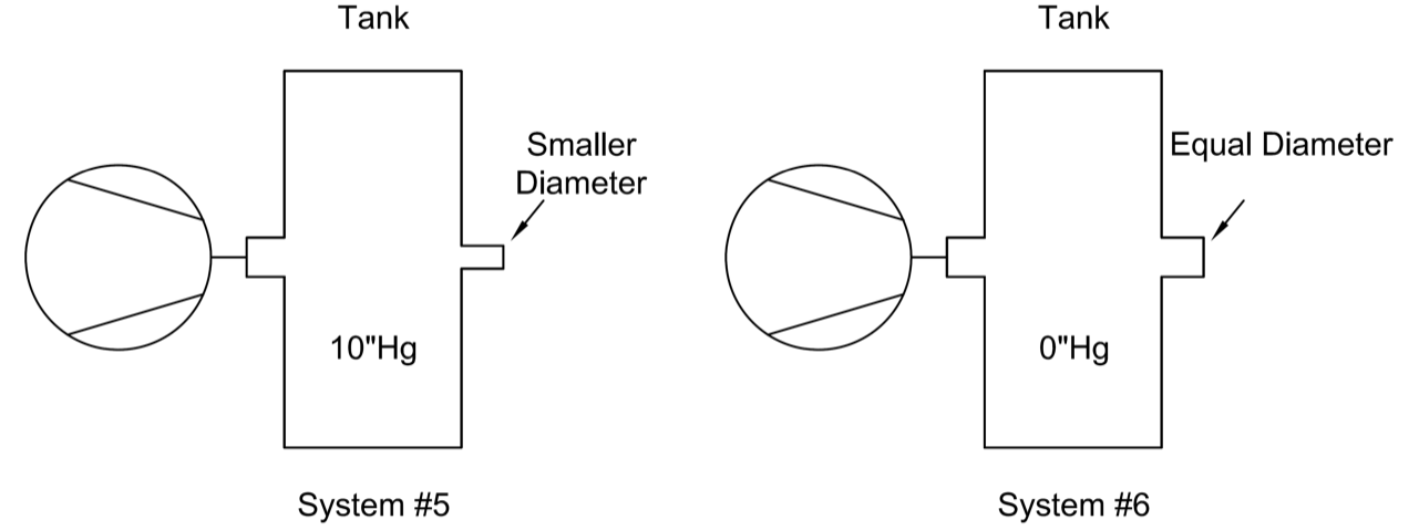
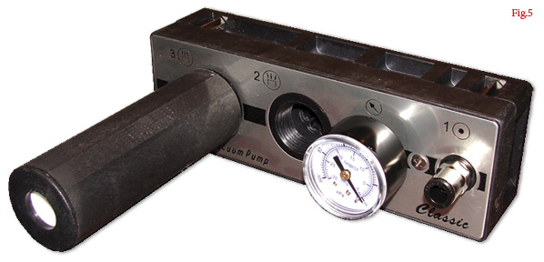
Now we will consider an application with more obvious open flow features. Figure 5 shows two identical vacuum tank systems using identical vacuum pumps. The difference between the two is the size of the vacuum entry ports of the tanks. System 5 is capable of generating a vacuum level of 10”Hg because the tank entry port is small enough that the flow is restricted at the tank inlet and the pump is able to compensate for the leakage to generate a vacuum level. On the contrary, system 6 has equal-sized inlet and outlet ports, so the flow in and out of the tank are about equal. This does not allow a vacuum to be created, so the vacuum level inside the tank is zero. This example is relevant to applications such as centralized vacuum systems, vacuum conveying, and leak testing.
CONCLUSION
This article covered key performance characteristics in a vacuum system – vacuum level and volumetric flow rate. Each were defined on their own and then tied together using realistic application examples. The content enclosed is meant to be an opinion educational guide to vacuum. All numbers and examples have been arbitrarily chosen.
Share this information.
Related Posts

Sponsor

Sponsors