A primer on Mobile Fluid Power
By Joe Raccosta, Fluid Power Sales Manager, and Micah Taylor, Mobile Fluid Power Manager, Milwaukee Division, Motion
Once during a discussion about a mobile fluid power application, a colleague kept referring to what he called “voodoo hydraulics.” This curious phrase illustrated the many and often misunderstood differences between mobile and industrial fluid power.
As with industrial fluid power, mobile fluid power automates a machine and makes it move. Most of the time you’ll find mobile fluid power in machines with tracks or tires that are outdoors in the elements. But mobile fluid power refers not only to the type of machine, it also refers to types of hydraulic components and circuits used to control the machine. This article discusses how mobile fluid power works and how it is different from industrial fluid power.
In most cases the human-machine interface between mobile and industrial equipment is very different. Many industrial applications are automated. Programmable logic controllers and programming allow the machines to run a large number of functions based on sensor or user inputs. Most of the time, with mobile equipment the human-machine interface is much more intimate. The movement of a lever or joystick or the push of a proportional thumbwheel directly affects the machine’s movement. It gives the operator the ability to get the “feel” of the machine, much like driving a car.
Another big difference between mobile and industrial equipment is the prime mover. Mobile machinery regularly uses the vehicle’s engine-driven system (its internal combustion engine) for the prime mover; in industrial applications, it’s usually powered with an electric motor. However, there is an overlap. For example, open loop pumps (vane and piston) are used in both segments but are more prevalent in industrial systems, whereas closed loop pumps are more frequently used in mobile systems. Screw-in cartridge valves are used in many manifold assemblies across both platforms as well. Both segments use cylinders, but mobile tends to use more welded and telescopic types than industrial. As far as fluid conveyance, mobile applications often operate at higher pressures and need hose with higher pressure ratings. They also require corrosion-resistant fittings for environmental protection, as well as abrasive-resistant hose because of machinery movement. Later in the article, we will describe some of the more common components found in a mobile system.
Unique Characteristics
As with other segments of industry, mobile fluid power has unique characteristics and challenges. Some of those characteristics are duty cycle, environment, modular size, and noise and shock.
Duty cycle. Duty cycle is the ratio of time a load or circuit is on compared to the time the load or circuit is off. The duty cycle on hydraulic pumps is the number of minutes in each hour the pump is under load. If you place a lower-efficiency, lighter-duty pump into a higher-duty cycle application, the life of the pump is compromised. Each subsegment of mobile equipment has varying duty cycles, and some applications may require higher-duty cycles than others.
Corrosion resistance. Mobile equipment operates within a wide scope of environmental conditions. Mobile equipment must be compact yet powerful, with performance unhindered by environmental factors like rain, snow, ice, dirt, extreme heat, or moisture. These environmental factors typically don’t come into play in the design or performance of industrial equipment. With these environmental challenges, mobile hydraulic components require anticorrosion agents for preventive measures.
Size, weight, and power output. Size, weight, and power output are crucial in mobile applications. Mobile components are typically smaller, modular, and lighter compared to industrial components. Take a reservoir, for example. On an industrial system, it is usually sized around three times the flow of the pump’s output, whereas in a mobile system the reservoir size could be as small as the output of the pump or less. Producing the power output required with less space and weight is crucial. That is why power density is a major factor in mobile hydraulic circuits. Power density is the power output per unit volume, or the power output as a ratio of the actuator size. Power density is one reason why hydraulics is so important to mobile machinery. Mobile systems require high-output power combined with minimum weight.
Noise, shock, and vibration. Mobile systems tend to have higher noise, shock, and vibration challenges because of improper human operation or extreme and rugged operating conditions. Because of the environment in which mobile systems operate, they generally do not have strict noise (dB) specifications like an industrial system and tend to operate at higher dB levels.
An example of shock occurs when a loader operator runs the bucket in “shake mode,” that is, starting and stopping the bucket’s movement quickly to break loose stuck materials. That sudden start-and-stop motion adds shock to the hydraulic system.
Vibration is another challenge from both the machine’s engine and terrain conditions. Uneven and rough terrain can cause vibration as well as pressure pulsations originating from the hydraulic system. Another factor is user error. Again, the operator can cause some of these issues by having the machine make sudden and erratic movements, leading to abrupt changes of pump displacement and actuator positions, causing additional vibration.
Now we’ll look at some common mobile fluid power components.
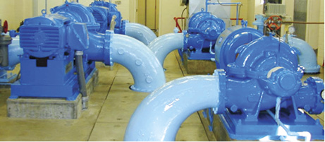
Pumps
Both industrial and mobile systems use gear, vane, and piston pumps. The main drivers behind mobile-component design are weight, space, environment, and performance characteristics. Historically, noise has not been a huge factor, but more stringent regulations and exports to Europe are changing that.
Piston pumps are the most expensive of the three types but offer the most control options and highest operating pressures. In general, gear pumps fall between the piston and vane on both operating pressure and price. They can be a bit noisy depending on the gear design. Vane pumps have historically been the least expensive type. They tend to operate at a lower noise level and offer a number of pump controls.
Before discussing pump controls, there must be a basic understanding of what fixed and variable displacement means. A fixed pump always has the same displacement no matter the pressure. The input speed at which the pump turns can change the output flow, but the physical displacement of the pump always remains the same. With a variable displacement pump, the oil volume output can change based on the displacement change. This can be done in several different ways with a variety of pump controls.
By far, the most common controls in the mobile world are the pressure compensator and load sense. If a pump is outfitted with a pressure-compensator control, it sits at maximum displacement until the prime mover is turned on. As the pump immediately creates flow, pressure starts to build. As the pressure builds to a predetermined setting, the pump mechanically destrokes, or reduces the pump displacement to zero. It stays at zero until a machine function is operated. At that point, the pump flows oil to the function as quickly as physically possible. One advantage of this system is that it reacts quickly. This type of control is a good choice for a mobile machine such as a telehandler, in which the operator wants no lag between joystick operation and a function move. The disadvantage of a pressure-compensated system is that it is always at the maximum compensator pressure setting, or high-pressure standby. So if high-flow low-pressure functions are run, the net result is a high-pressure drop between the pump and actuator, resulting in heat.
Load sense is a variation of the pressure-compensator control but takes it a step further. Just as with the pressure-compensator control, when the machine is off, the pump sits at maximum displacement via a bias spring. When the prime mover turns on, the pump starts to create flow and pressure builds. But instead of reaching the compensator setting, the load-sense control destrokes the pump at a lower predetermined setting, referred to as low-pressure standby. A common low-pressure standby setting is
300 psi (21 bar).
The advantage of the load-sense pump is that it is very efficient if used on a machine that can see many different load conditions or pressures. The disadvantage is that you must use a load-sense valve with the pump. That adds cost and complexity to the overall system. There are many controls available for mobile equipment including horsepower limiting, electroproportional displacement, hydraulic pilot control, and more. But the load-sense system is one of the most popular on mobile equipment.
It’s not always the case, but in general it seems piston and gear pumps have taken over the mobile market. Many applications can run between 3,000 and 4,000 psi (207 and 276 bar) maximum operating pressure, with many maxing out at 3,000 psi (207 bar), making the gear pump a possibility depending on the control scheme. The outlier is the hydrostatic drive pump that routinely has a maximum operating pressure of up to 6,000 psi (414 bar).
Mobile Directional Control Valves
Among all the product categories, the directional control valve probably differs more than any other. It is common in that it can control the direction and flow of oil. But virtually everything else is different in size, shape, weight, corrosion-resistant options, electrical connectors, and so on. There is a gray area, because it is still common to see small industrial valves – sizes D03 and D05 – on mobile machinery.
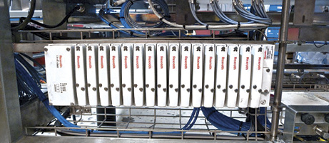
Mobile directional control valves come in two forms: monoblock and sectional. A monoblock valve has one body but can have up to eight spools within that body. Many are available in tandem, parallel, or series circuits. These valves are less expensive but also less flexible. Monoblocks are a good choice for equipment manufacturers that use the same valve repeatedly.
Sectional valves have an individual spool in each body, or section. The sections are held together with tie rods. Typically eight to twelve sections can be stacked together depending on the particular valve’s manufacture and size. This type of modular valve allows for many different combinations of options, making it an attractive solution for end users and equipment manufacturers alike.
There are two types of mobile valve circuits: open center and closed center.
Open center. Open-center circuits consist of a fixed-displacement pump and an open-center type mobile directional control valve. The fixed pump (typically gear) creates constant oil flow, which flows through the directional control valve and back to tank at a low-pressure drop. When the valve is operated, the main spool moves and starts to cut off the flow to tank and redirect it to the valve work ports. As the spool continues to stroke, more oil flow is directed to the work port and less to tank. When the spool strokes fully, 100% of the flow is redirected to the work port.
Within the open-center valve platform, there are three common circuit options, described as parallel, tandem, and series. The schematic symbols of each circuit show the pressure, neutral, and tank passages
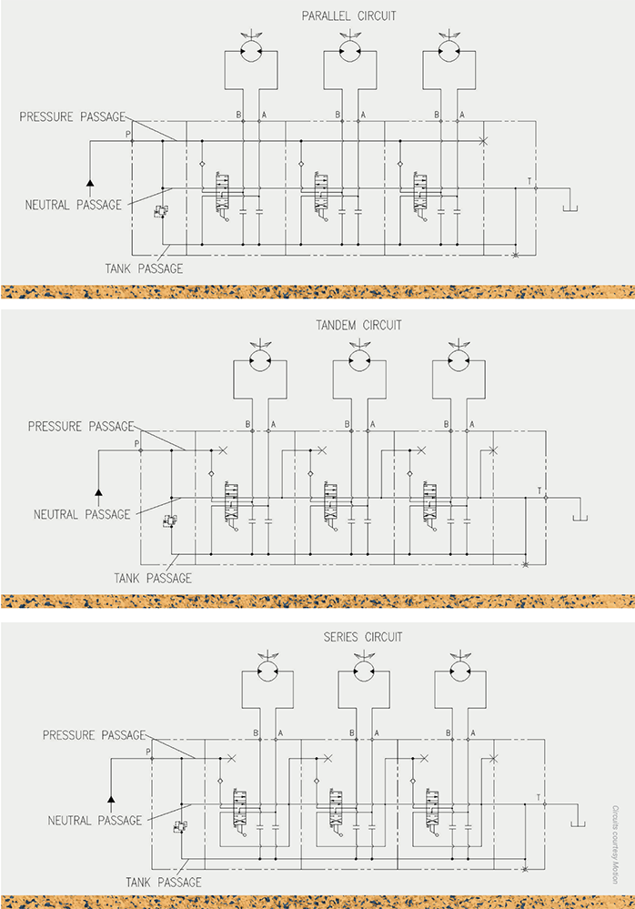
In a parallel circuit, the main inlet pressure is connected to all the spool, or section, P ports through one main pressure core or passage. In this case, if multiple functions are run, the oil can take the path of least resistance and cause a function to slow or stop.
In a tandem circuit, the main pressure passage is cut off between each section, allowing oil to be directed through a neutral passage only. If each section in a valve stack is tandem, the upstream section will always have flow priority. The oil coming out of the actuator (cylinder or motor) is directed by the spool back to the tank port via the tank passage.
In a series circuit, the pressure passage is cut off between each section but allows oil to run through the neutral core. After the oil returns from the actuator (cylinder or motor), it flows over the spool, but instead of going back to tank, it is routed to the next section’s pressure passage. This allows 100% of the oil flowing into the valve to go through each actuator and run them in series.
Closed center. Closed-center valves do not allow oil to flow through the valve and back to tank but will block the flow completely. In cases where this type of valve is used, a variable-displacement pressure-compensated pump is required. When the prime mover is turned on, the pump will destroke at a predetermined pressure. When a function is operating, the pressurized oil moves the actuator responsively.
Load-sense valves are more complex. They are closed center and must be used with a variable-displacement pressure-compensated load-sense pump control. The added load-sense function works like this: When the valve is operated, a load-sense signal is generated and directed back to the pump control via a separate load-sense line, allowing the pump to stroke and develop flow. This type of system is an advantage when there are varying flow and pressure requirements. The correct flow is provided at load pressure plus the set stand-by pressure.
Load-sense systems can be split into two technologies: precompensated and postcompensated. The precompensated valve is the original technology. The disadvantage is that when the machine calls for more flow than the pump can offer, the highest pressure function slows or completely stops (path of least resistance). The operation of the postcompensated valve is different. When the machine calls for more flow than the pump can offer, all the functions slow down proportionally. The main advantage of the postcompensated system is it does not allow any one function to stop, which gives the operator more predictive and consistent control of the machine under varying operating conditions.
Steering Control Units
Steering control units, often referred to as steering orbitrols, are components much more frequently found in a mobile application than in an industrial application. They are used in conjunction with a column and wheel to steer a machine. Applications include lawn and garden, lift trucks, construction, forestry, agricultural vehicles, dump trucks, forklifts, and tractors.
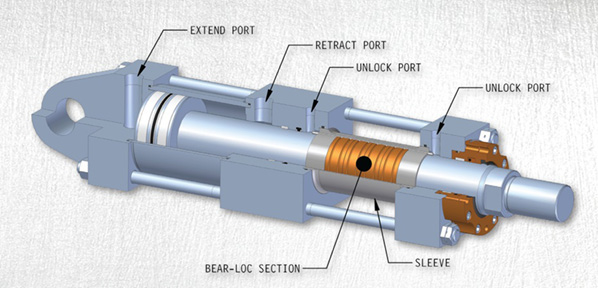
Cylinders
Cylinders are available in an infinite number of sizes, configurations, and complexities. There are standard “off-the-shelf” cylinders as well as customized cylinders with mounted manifolds for load holding or other hydraulic circuits. Like industrial fluid power systems, cylinders in mobile systems are very application-specific, including the telescopic cylinders used on applications such as dump trucks. Most of the cylinders that we see on mobile equipment are of a welded design, versus the tie-rod and mill-type cylinders found on industrial equipment. Not to exclude the telescopic cylinders used on applications such as dump trucks.
Motors
Motors, like pumps, are available in vane, gear, and piston design. The performance and cost comparisons between them are the same as well. No matter what the technology used, hydraulic motors seem to cross over the most out of all the product categories. Motors come in several mounting configurations and are used to turn tracks, wheels, augers, mixers, swing drives, and more on a variety of mobile equipment.
Hydrostatic Transmissions
Another technology attributed to mobile hydraulics is the hydrostatic transmission. Often it is used as a ground drive to propel machines but found on many motor circuits where reversing direction and variable flow is required.
The hydrostatic pump and motor both have two pressure ports, A and B. The ports are connected or “looped” together so that the oil that comes out of the motor goes directly back into the pump. The pump itself can supply oil out of the A or B port. That is what allows the motor to reverse. What makes the motor unique is that it often has a hot-oil shuttle built right into it that strips oil out of the loop so it can run through a filter or heat exchanger. In the hydrostatic pump, a small gear pump – referred to as the charge pump – replenishes the oil that was stripped away by the hot-oil shuttle and the case drains.
Hydrostatic transmissions are used in applications like tractors, forestry machines, golf course maintenance equipment and more.
Cartridge-Valve Technology and Custom Manifold Integration
Cartridge valves were created because equipment manufacturers demanded more flexibility in the design of their hydraulic systems and the industry demand for refinements to their line-mounted hydraulic systems to a more compact design. The result is a more simplified installation appearance of the system and fewer hydraulic hoses, fittings, and mounting brackets, eliminating many leakage problems.
Cartridge valves are commonly used to control oil pressure, direction, and flow. Valves are either spool, poppet, or ball check design. Screw-in cartridges are very compact and produce inexpensive circuits that are reliable and easy to maintain. Screw-in cartridges are most often part of a machined manifold but also are available in individual bodies. Custom machined manifolds with cartridge valves compress the overall envelope size by combining valving and plumbing into one complete package.
Installation and maintenance of custom manifolds are more simplified when compared to traditional, line-mounted valve systems. The need to connect valves by hydraulic hoses and fittings is reduced using internal passages machined into the manifold block. By designing one or more manifold blocks into a system, the time and cost of installing the hydraulic system are much less than traditional, line-mounted valve systems. Advantages for OEMs using a custom manifold block with cartridges are greater design flexibility, lower installed cost, smaller package size, less external leakage, easier troubleshooting, easier maintenance, organized plumbing, and lower noise levels. Compact manifold assemblies reduce the system size and weight, allowing for smaller, more efficient mobile applications.
The differences between mobile and industrial hydraulics have evolved in response to the performance and environmental requirements of the equipment being produced. These industries are evolving with various demands of technology, flexibility of systems, cost savings, and efficiency requirements. Fluid power products and solutions specific to mobile or industrial equipment continue to evolve. Although hydraulic components serve similar functions across both segments, understanding differences between these components’ functionalities, their applications, and how the machinery operates benefits equipment users and designers alike.
Share this information.
Related Posts


Sponsor

Sponsors