Ch-ch-ch Changes: How Evolving ISO Standards Affect Hydraulic Flanges
By Robert Mackey, President, MAIN Manufacturing
The world of large hydraulic connectors is dominated by flanges of one sort or another. If you need to raise a city-block-square offshore oil platform 30 meters into the air, or sit in the axle of a dump truck to work its brakes, or work plates of steel, aluminum, and other materials to a usable dimension, you are probably working with flanges.
Three ISO standards concern themselves with hydraulic flanges: ISO 6164, ISO 6162-1, and ISO 6162-2. There are also several national standards and several special manufacturers’ designs. This article discusses recent changes to ISO 6164.
The ISO 6164 standard
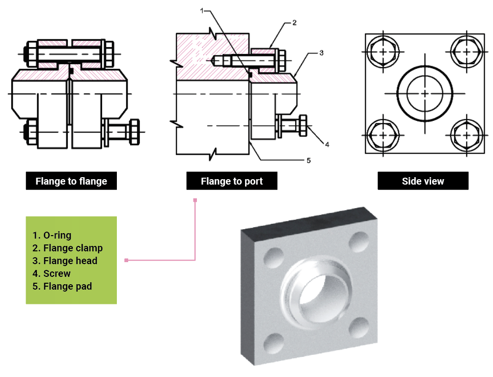
The ISO 6164 hydraulic flange standard was first adopted by the International Standards Organization in 1994 at the same time as ISO 6162 (SAE J518). It describes a hydraulic connector called a flange that can connect to a mounting pad or similar ISO 6164 flange. Although the standard’s title indicates that it is a one-piece fitting, it actually consists of three pieces – a flange head, a flange clamp (collar), and an elastomeric seal. The one piece refers to the fact that the flange collar is not split into two sections like the ISO 6162 flange. It uses an elastomeric seal.
ISO 6164-1994 had two maximum pressure ratings: 25 MPa (3,600 psi) and 40 MPa (5,800 psi). The standard covered size ranges from DN10 (about 3/8 inches) to DN80 (about 3 inches). It had a minimum design factor of 2.5. It was based on an earlier DIN standard. The DIN standard had several key design elements in which the dimensions were “to be determined between the manufacturer and the user.” Even with this flexibility the standard was not widely adhered to, but many companies used the ISO 6164 mounting pads as a basis for custom, nonstandard components. Flanges based on the ISO 6164 standard found their way into many industries, such as offshore, chemical, and steel mills.
For identification purposes, the most consistent feature about flanges based on ISO 6164 is the mounting pattern. A mounting pattern consists of the mounting hole spacing, hole quantity, and through hole or tap size. Many international experts considered that “based on” is different than “according to.” “Based on” to them means that the items listed do not conform to the standard but are similar in function, though not necessarily form and dimension. Flange heads and clamp styles vary significantly and can be merged to a one-piece design, but the mounting pad dimension and screw sizes are the same. MAIN Manufacturing makes flanges to the standard, but our “based on” variation is one piece, combining both flange head and flange clamp, and is a more popular design. The only drawback of using the mounting pad is that it must be measured fairly accurately (± 0.25 mm [±.010 inches]). The reason is the whole numbers of the measurement can be based on the centerline of diagonal holes (bolt circle), or adjacent holes (bolt square). Those base numbers may be in the imperial or metric systems. Between 98 mm bolt circle (2.728 inches bolt square) and 4-inch bolt circle (2.828 inches bolt square) are seven standardized patterns.
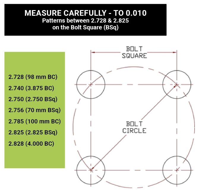
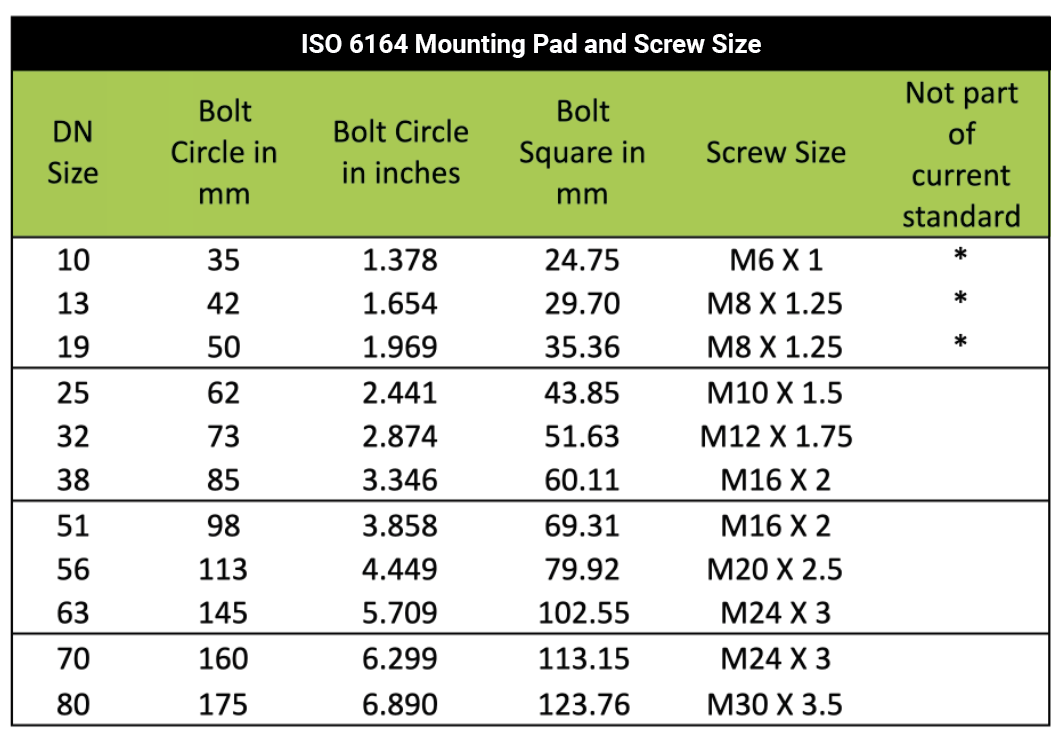
ISO 6164 flange mounting pad patterns are based on bolt circles. Other flange standards such as CETOP and some company standards, such as some of those by Oilgear, use bolt circles as well. Flanges to Japanese standards, such as B2291, and some company standards, such as the old Vickers flanges, use bolt squares. If measuring an existing item, there are manufacturing tolerances to consider as well. MAIN’s website (https://mainmanufacturing.com/pdf/measure.pdf) and Fluid Power Journal’s website (https://fluidpowerjournal.com/?p=8506) provide tips for making the measurements. Unfortunately, you cannot rely on manufacturer’s specifications because several manufacturers include items like flanges larger than DN 80 under the banner of ISO 6164 that are not based on any elements of ISO 6164. Flanges said to be to ISO 6164 that have mounting pads not included in the box at the right are of dubious origin. The box shows ISO 6164 mounting patterns per size.
Changes in ISO 6164-2018
Several items have changed in ISO 6164-2018. These changes include the series and sizes offered, flange-head sizes, assembly instruction changes, testing, and materials. Components manufactured to the 1994 edition can be used with the 2018 components if both are manufactured to the appropriate standard, but it might be advisable to not interchange them. The changes taken together allowed the design factor to be increased from a minimum of 2.5 to a minimum of 4. A design factor is the minimum multiplier from design loads that the designer uses to account for installation variability, such as actual material and dimensional values (not theoretical values); material changes such as corrosion, fatigue, and wear over the life of the component; unexpected load increases such as pressure spikes and gauge variability; and a host of other issues. It helps account for lack of knowledge concerning the specifics of the actual situation. If a user decides to encroach into this area, it may work for a period, but Murphy says that it may fail at the worst possible time.
The 1994 edition of ISO 6164 specified two maximum-rated working pressures series: 25 MPa and 40 MPa (3,626 psi and 5,802 psi). The 25 MPa series used the same mounting pads as the 40 MPa series but with different clamps and flange heads. The 2018 edition eliminated the 25 MPa series to avoid confusion and to decrease the possibility of interchanging components from other series. The maximum rated working pressure increased 40 MPa to 42 MPa (5,802 psi to 6,092 psi) to correspond to common system pressures that exist in the marketplace.
Both ISO 6162 and ISO 6164 flanges are generally used in larger connections. The ISO 6164-2018 eliminated the DN 10 through DN 19 sizes due to lack of use. These sizes are covered by other connector types.
The new edition also decreased the depths of the flange-head counterbores on several sizes of clamps to increase the strength of the clamp. This change is relatively minor in the 0.6 mm (.023 inches) or less range and can be hard to see.
Two flange-head sizes in the new edition have larger outside diameters. The DN 63 and DN 80 sizes change by up to 6 mm (.24 inches) in diameter. The new edition did not change the outside diameter of the counterbore in the flange clamp, and the ISO 6164 clamp counterbores will physically accommodate the new flange heads.
Another change is in the material. The 1994 edition called out material equivalent to Fe 510C steel. In the thicknesses involved, the yield strength ranges from 295-345 MPa (43-50 kpsi) and tensile strength ranging from 450-630 MPa (65-91 kpsi). The new edition calls for a minimum yield strength of 330 MPa (48 kpsi). This increase makes several grades of stainless steel, such as AISI 304, 304L, 316, and 316L, nonviable options without extensive cold working, which reduces the corrosion resistance to some extent. It also means that lower carbon-content carbon steels should also be cold worked to achieve the increased yield strength as well.
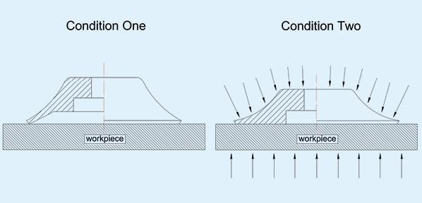
Another big change is in the assembly procedure. The 1994 edition did not really have any assembly instructions other than matching the component series and sizes and using the system fluid to lubricate the O-ring. The screw torque values were for “lubricated” screws, meaning oil of some sort. The 2018 edition has an annex dealing with assembly and proper screw tightening in X pattern. It also requires the use of molybdenum disulfide paste lubrication under the screw head and the screw threads. The amount that the screws are tightened and torque values changed as well, both increasing and decreasing. This is critical to achieving the higher design factors and not snapping the screw while tightening it.
Creating ISO standards
This article discussed the ISO 6164 standard and its revisions in the new edition to give designers and users insight into when to question suppliers and manufacturers. The standard is the basis for many special components, some of which have been proven over long usage and testing. It is a good idea to buy the standard and know what is in it instead of relying on sales people for the information.
Interested fluid power professionals can consider joining SAE or NFPA technical committees, where standards are proposed and modified. Within fluid power, the SAE committees tend to be U.S.-based, while NFPA handles the U.S. technical advisory groups to ISO. Members include users, producers, distributers, educators, and other interested parties. For more information, visit www.sae.org or www.nfpa.com.
Share this information.
Related Posts


Sponsor

Sponsors