Five Steps to Efficient, Error-Free Process Adjustments
By Steve Bain, Industrial Segment Sales Manager – Food and Beverage, Festo Corp.
Modern automation systems increasingly need to adapt to various products in multiple sizes and configurations. And one result of this variability is having to make frequent process adjustments to flow, pressure, end-stop limits, and machine speed, to name a few. All too often, however, this ongoing need to make process adjustments opens itself up to unwanted device tampering, which can easily cause a machine or process to spiral out of control.
Fortunately, there are ways to ensure all process adjustments are effective and correct. A five-step process can ensure error-free process adjustments of pneumatic components.
Step 1: Eliminate unnecessary process adjustments.
Your first step is to eliminate process adjustments wherever you can. For example, you can weld or secure machines in place if they never have to change position. Other solutions involve the use of fixed-orifice flow controls, correctly sized products, modular valve manifolds, and cylinders with self-adjusting cushioning capabilities.
- Fixed-orifice flow controls. Embedding fixed-diameter orifices into valve manifolds permanently sets an actuator’s speed, eliminating the need to make process adjustments.
- Proper dimensioning. Using correctly sized components avoids having to use pressure regulators or flow controls to reduce actuator speed or force.
- Modular valve manifolds. Modular manifolds with multiple valve sizes let you easily optimize the size of the valve for each application, reducing the need for flow controls.
- Self-adjusting features. Pneumatic cylinders with automatic, self-adjusting cushioning features ensure optimal performance without adjustment screws. Festo PPS self-adjusting cushioning is available for a wide variety of actuators.
- Lockable adjustments. MS regulators can be locked in position once set, preventing unauthorized adjustments.
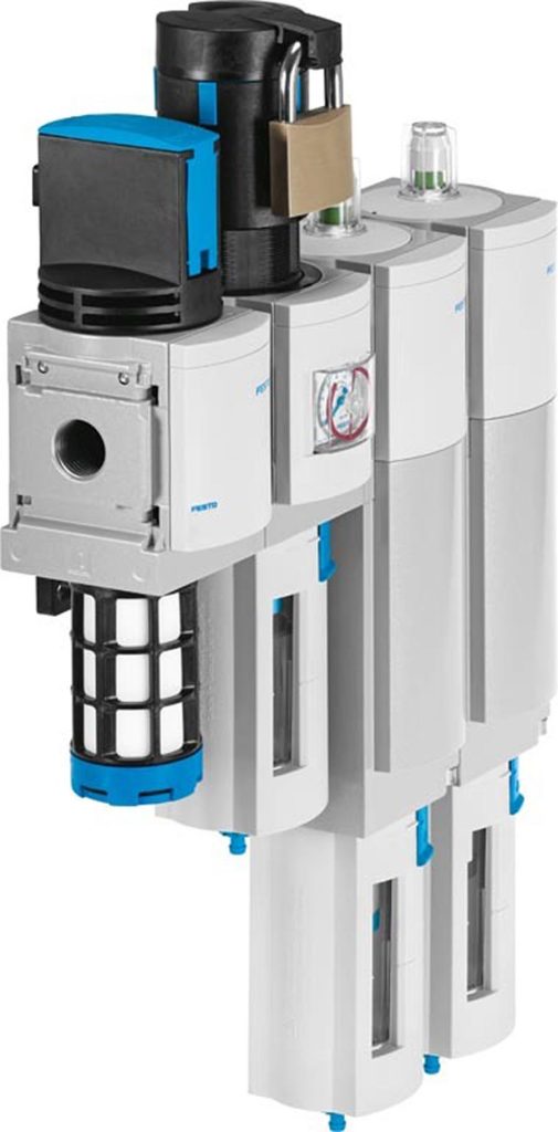
Festo MS Series lockable regulator.
Step 2: Use automation to eliminate human error.
Your next step is to specify pressure regulators, actuators, and other components with built-in automation capabilities, removing human error from the equation. For example, proportional pressure regulators like the VPPM automatically adjust the output pressure via a 0-10 volt or 4-20 mA signal from the programmable logic controller. Thanks to its two-stage circuit and multisensor control, this device provides precise, reliable pressure regulation. You can also preset parameters like pressure, piston speed, and rotational speed with the push of a button – no technical specialists required.
Other examples include advanced electric or servo-pneumatic actuators, which you can configure according to your exact speed and force requirements without additional pressure regulators or flow controls, as well as intelligent servo motors. The SMS electric actuator for example, combines a motor, controller, and electric axis package, facilitating changeovers and enabling fast, consistent process adjustments.
In addition to the examples above, look for digitized pneumatic solutions like the Festo Motion Terminal VTEM. By combining pneumatics and electronics in a single package, the VTEM functions as the world’s first app-controlled valve, enabling you to digitally define, control, and analyze valve function, flow rate, pressure, and other process parameters:
- Airflow control. The VTEM removes separate flow control valves on the actuator, allowing you to set tamper-proof travel speeds at the push of a button. It also provides the option to implement new motion sequences like dynamic flow control.
- Pressure levels. With the option to input pressure levels, the VTEM saves energy. Simply select the movements and set the pressure to the level of your choice. You can even control the speed by adjusting the flow control valve setting.
- Leakage diagnostics. With separate diagnostic cycles and defined threshold values, the VTEM lets you detect and localize leaks, minimizing your downtime.
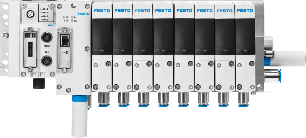
The Festo Motion Terminal VTEM.
Step 3: Implement sensors for condition monitoring.
The third step is to monitor and detect the status of processes that may be affected by any process adjustments. Examples include:
- Differential pressure monitoring solutions that can help determine when you may need to replace filters.
- Pressure sensors and switches that can communicate with the programmable logic controller, verifying if a process is within the desired pressure range.
- Flow sensors that monitor the amount of consumed air, indicating if a process is performing as expected.
Step 4: Maintain centerlining.
Of course, automatic process adjustments are not always possible. If you do need to make a manual adjustment, we recommend using a numerical scale to ensure the adjustments are consistent. For example, look for flow control components with position markings or digital flow meters. The GRLSA one-way flow control valve includes a labeled adjustment ring, while SFAH, SFAB, and SFAM flow sensors feature an integrated display, ensuring you achieve your desired flow rate.
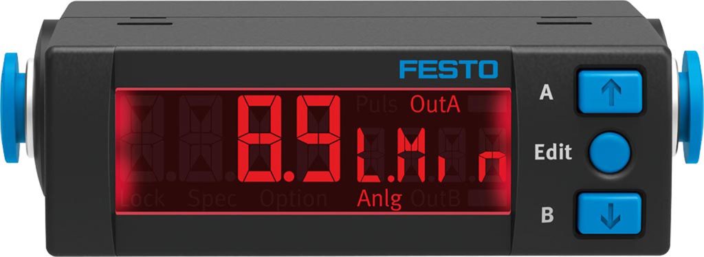
The Festo flow sensor SFAH.
Step 5: Take advantage of red and green visual indicators.
The last and final step to ensure error-free process adjustments is to use pneumatic components with red and green indicators. These features offer a quick and easy way to validate when processes are performing as expected.
For example, MA-RG pressure gauges include an adjustable red and green range, providing an extra level of safety when monitoring your compressed air usage. Units include red segments above and below the pressure gauge scale, as well as a printed green segment. Thanks to this colored demarcation, you can immediately identify when the pressure is or isn’t in its permitted tolerance range. These gauges can handle ranges from vacuum to 16 bar and include an optional flange design for panel mounting.
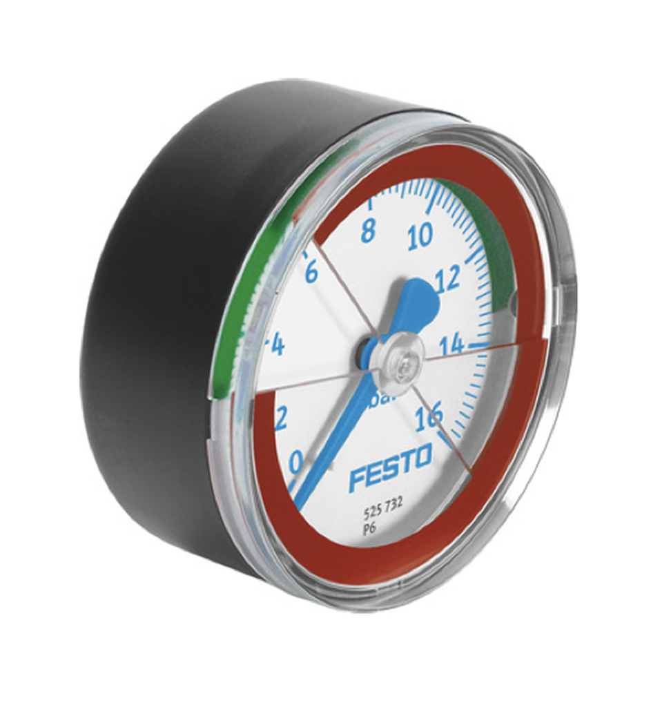
The Festo MA-RG pressure gauge.
Similarly, MS Series components, which include pressure regulators, on/off valves, soft-start valves, pressure sensors, and flow sensors, feature an integrated red and green scale that displays the output pressure. SFAM flow sensors, for example, feature an illuminating display that turns red, indicating when the flow is out of the desired range.
Although making process adjustments is inevitable, it doesn’t have to result in unwanted device tampering or machines and processes spiraling out of control. By following these five steps – which includes using components with automatic adjustment capabilities, implementing sensors, using visual indicators, and more – you can ensure all process adjustments to your pneumatic components are effective and correct.
For more information, visit www.festo.com.
Share this information.
Related Posts

Trelleborg Signs Applied Power as Distributor

Without Skilled Tradespeople, Who Builds It?
Pure and Simple: A Servo Valve that Streamlines Hydraulic Control
Fluid Power Professional Publishes Historical Fluid Power Book

Keys to Success: 8 Building Blocks of Smart Fluid Power Systems

ESA Offers Webinars on Leadership, Websites
Sponsor

Sponsors