Flow Control: If In Doubt, Think About…Energy

I see some of you forgot to bring your calculators with you. We’ll wait right here and chat a bit while you go fetch your equipment…
I stated in my first article, “Focus on Energy,” that I could have lifted a load that required 25 hp using only 12 hp and that I would discuss it in a future article. Well, the future is now. We will need some background information that we will discuss while we are waiting for the others to come back.
When covering the material for taking the CFPS exams, I remind people about some of the laws of physics, namely the relationship between effort, work and power. If I lean up against my file cabinet, I will be putting in some effort, but I will not be doing any work. “Work” is defined as “effort over distance,” so unless I actually move the file cabinet, all my effort will technically have done no work. If I am able to tilt the cabinet up and then realize I forgot to bring the hand truck and set it back down again, I will have done some work, but then the work would be undone because the cabinet is in exactly the same spot as before I started. The net result is zero work with a lot of effort.
An illustration of this is what I am told about the DeLorean “Back to the Future” ride that used to be at a famous amusement park. The customers got into the car and closed the doors. A marvelous hydraulic system tossed them up and down, back and forth, this way and that while they watched a movie screen that depicted the virtual ride. When the ride was over, the doors opened and everybody got out… right where they started. It took 1000 hp to operate the ride, but no useful work was done. Every motion was undone. So, where did the energy go? It all went into Btu’s through a huge heat exchanger. The ride was 100% inefficient. Despite all the movement, everyone landed right back where they had started. No work was accomplished. The thrill ride dumped about 42,000 Btu’s per minute into the atmosphere.
The point is this: when we lift a load, we give it potential energy. When we set it back down again, we dissipate that energy, usually in the form of heat.
Now, if everyone is back with his or her calculators, we can begin.
In the earlier article, we had an upward acting press with a 32,000-pound platen that had to be lifted at a rate of 5” per second. We did the math and found that (32,000 / 550) * (5/12) = 24.24 or about 25 hp. (This will give you a chance to synchronize your calculators.) Reflecting on the DeLorean illustration, it should occur to us that when the press operators turn off the machine and go home for the evening, the 32,000-pound platen is right where it was when they started up in the morning. A lot of energy had been put in, but it had all been undone.
Once the platen is lifted, we could just let it drop, and we would have a dramatic illustration of the fact that the potential energy has become kinetic when the platen hit the bottom and suddenly dissipated all its energy into the floor of the building. To avoid this show, I had added a pressure compensated flow control to limit the speed of descent.
We know that when hydraulic fluid goes from high pressure to a lower pressure without doing work, the energy is converted into heat. So, here are the questions. Given a 6” bore cylinder controlling a 32,0000-pound load and lowering it at 5” per second, what would the pressure be upstream from the flow control? What would be the flow rate across the flow control? What would be the hp loss across the flow control? What would be the total Btu load added to the fluid if the load dropped 72”?
No, I’m not going to give you the answer. You have to figure it out for yourself. This is interactive journalism.
Well, alright, if you’re going to whine, you can find the answers at the end of the article.
In any case, compare the hp loss to the hp required to lift the load. Do you see some similarities? The math tells us that all the energy we put in was taken out again in the form of Btu’s; hence the need for a substantial heat exchanger. In the actual system, I was using a double-acting cylinder, and so I was pushing the cylinder down adding to the pressure drop across the flow control. I was actually wasting more energy as I lowered the platen than I had put into the system as I raised it.
What if we could find a way to save and store some of the energy as we lowered the platen? Well, with the right flow control system, we can.
Remember, we are not necessarily talking about the least expensive system to design or purchase. We are talking about a more efficient system to operate using a smaller pump, a smaller electric motor and a reduced heat load, the combination of which may indeed mean a competitively priced system.
To do our magic (actually, there is no magic, just math), we will need to return to the lowly and often unappreciated equal displacement flow divider. Only in this case, it will have triple duty; once a flow combiner, then a pressure intensifier, and then a flow amplifier. We will also need an accumulator, a pressure-reducing valve, and a pump producing half the flow as before.
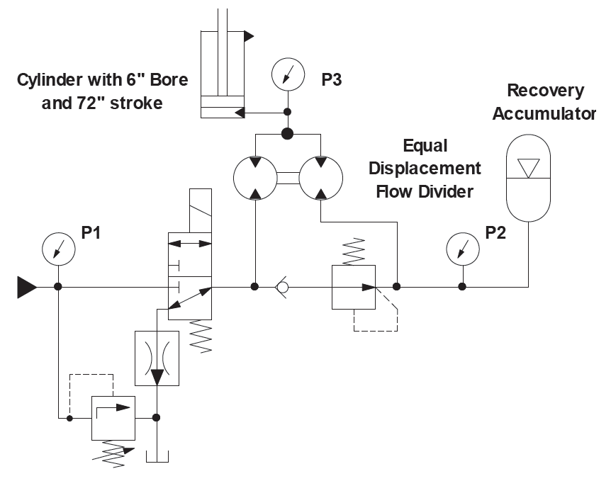
The displacement flow divider is placed in the line going to the blind end of the cylinder with the combined flow going to the cylinder. The two ports opposite the combined flow port are separated by a non-relieving pressure-reducing valve set at a pressure that is a little higher than what is required to lift the load. Upstream from the reducing valve, the port is connected to the directional control valve. Downstream from the reducing valve, the port is connected to the accumulator. The accumulator has a gas volume of 15 gallons and is pre-charged to 760 PSI.
We will go step by step as we activate the system referencing the drawing above. Keep your calculator handy and your brain clear.
The first time we energize the directional control valve, fluid is sent to both sides of the flow divider and also to the accumulator. The pressure-reducing valve is a normally open valve and so it does not come into play at this point. The easiest flow path is into the accumulator, and so the accumulator begins to fill until it reaches the pressure necessary for the fluid to rotate the flow divider and begin to lift the load. The cylinder extends at half the desired speed.
When the cylinder reaches the top of its stroke, the pressure rises to the setting of the reducing valve, which then closes, and the system rises to the relief valve setting.
What happens next is where it gets exciting. Are you ready? We de-energize the directional valve, and the cylinder begins to retract. Flow is directed to the inlet of the flow divider where it is split evenly through the divider. The reducing valve remains closed because of the pressure in the accumulator, and so half the return flow is diverted into the accumulator. The remaining flow passes through the directional valve to the pressure compensated flow control. As the cylinder descends, the pressure in the accumulator rises.
As the accumulator pressure rises, what happens to the pressure of the fluid passing through the pressure compensated flow control? Anybody want to answer? Yes,
I see that hand. Right! The pressure continually drops as the accumulator pressure rises. The flow divider is responding as a pressure intensifier.
As the cylinder reaches the bottom of its stroke, the accumulator pressure approaches twice the load pressure, and the return line pressure approaches zero.
Now we are ready to go into production. We energize the directional valve and something amazing happens. The pressure at the power source (P1) is near zero. The accumulator pressure (P2) is at twice the load pressure (P3). The flow from the pump enters one side of the flow divider while the other side is driven by the stored energy in the accumulator. Surprise! The cylinder extends at twice the rate that would be expected from the pump flow. Our lowly flow divider has become a flow amplifier. The pressure in the accumulator continually drops and the pressure at the source continually rises until the cylinder reaches the end of its stroke.
This process will repeat from now on. We will lift the load at the desired speed and, using the stored energy in the accumulator, we will do it with half the pump flow. In this illustration, we will actually store about 70% of the potential energy of the platen. The maximum pump pressure will still be what it was but only as the cylinder reaches the end of its stroke.
Flow control is a necessary part of our arsenal of fluid power components. We need to use them wisely with the best interest of the user in mind, including the cost of operation. If you must use a flow control and are not sure exactly what approach to take, remember,
“If in doubt, think about… Energy.”
1132 psi
What would be the flow rate across the flow control?
37 gpm
What would be the hp loss across the flow control?
24.4 hp
What would be the total Btu load added to the fluid if the load dropped 72”?
248 Btu’s
Share this information.
Related Posts


Sponsor

Sponsors