Get Smart: Digitized Vacuum Ejector Bolsters Predictive Maintenance

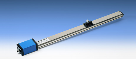
The piCOMPACT SMART vacuum ejector.
By Andrea Bodenhagen, Communication and Content Manager, Piab
Predictive maintenance is usually defined as monitoring the performance and condition of equipment during normal operations. With vacuum ejectors, being highly efficient, reliable, and small enough to integrate is no longer enough. Vacuum ejectors powering robotic gripping systems such as suction cups and foam grippers for pick-and-place applications are the interconnection between the gripping unit and the robot, and they can provide insights into both sides to ensure a smooth-running system.
When digitizing its flagship product to a smart version, Piab focused on supporting the requirements of predictive maintenance. The result was the piCOMPACT23 SMART ejector, which boasts technology to keep systems up and running at the maximum possible level while minimizing energy consumption.
Connectivity allowing communication between devices and the cloud permits the collection of data that simplifies maintenance and enables real-time settings adjustments without resetting the entire system. However, in an industrial landscape built with a plethora of different fieldbus protocols and no standardization in sight, it is difficult for suppliers to know where to start. With various countries and industry segments all presenting different preferences, the challenge was to find solutions that suit as many as possible. Piab decided on connectivity of the piCOMPACT23 SMART ejector through an IO-Link.
IO-Link bypasses this problem because it is not a fieldbus but a generic communication technology that fits any type of fieldbus. IO-Link is the first worldwide standard (IEC 61131-9) for IO technology used for sensor and actuator communication. The powerful point-to-point communication is based on the long established three-wire-sensor-and-actuator connection and places no additional requirements on the cable material.
Offering fieldbus independence, IO-Link is a further development of existing, tried-and-tested connection technology for sensors and actuators. It offers automated parameter setting and enables operators to read and write parameters for various features even during operation. Such a degree of process overview in real time means operators can deal with many potential issues before they have any real impact on production. The opportunity for system diagnosis allows operators to identify problems and correct them more easily and quickly. This has the potential to lead to greatly improved productivity.
One of the key factors behind this diagnostic ability is that, contrary to conventional technology, IO-Link offers a data-storage function. This enables operators to quickly establish if a device or operation has failed and to identify the failure’s cause. If a new, identical substitution device is connected, the parameters of the previous device transfer automatically.
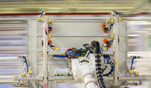
Suction cups handle a metal part in an automotive press shop.
Sensor integration
In vacuum systems, big data analysis requires measurements of various characteristics. Sensors collect information for condition monitoring and predictive maintenance. They measure direct operation characteristics of the vacuum ejector for quick detection of potential operational issues such as system leakage. Users can set trigger points that indicate when maintenance is needed. This allows preparation and the exchange of parts, avoiding unforeseen shutdowns.
Piab equipped piCOMPACT23 SMART with diagnostic sensors that support predictive maintenance by measuring system temperature, voltage, acceleration, cycle counts, and self-check features. Changes in the measurements can indicate something broken in the robot cell or plant.
A sensor shows the real operating temperature and provides fast information in case it moves out of range, which may indicate problems in the closer environment of the ejector. This feature was integrated as an easy-to-detect warning signal of issues with other system devices that cause temperatures to rise. A voltage sensor controls the power input and determines the operational status. It can warn of damages to the system due to low power.
Keeping vacuum-based robotic gripping systems clean is an important parameter to predicting maintenance. In dusty applications, vacuum filters can contaminate over time, leading to unwanted vacuum-pressure drops that slow the process or even give false signals. A way to monitor this is to keep control of the vacuum system’s built-in pressure-drop level. If the level starts to drift from its initial status, it means the system is starting to clog.
Another way to predict maintenance is to track the time to evacuate to a certain vacuum level. It can show if the system suffers from leakage and needs service.

Vacuum-based robotic gripping systems in the automotive industry.
Improved safety features
Operational safety plays an important role in the running and maintenance of machines. This led to the development of separate power domains for actuators and sensors. The sensor power is also used as main power for the unit. The separation occurs with optocouplers. The sensor power activates separately by the operator for maintenance or troubleshooting in the robot cell while leaving actuators disconnected from power supply. Operators are not endangered by moving parts in case of, for example, a short circuit. The advantage of the separate power domains is that it allows the use of compact-style ejectors without separate valve stations. This reduces the cost of installation, and expensive workarounds or add-on modules to compact ejectors are usually not required.
A second safety feature is a complementary bit that needs to be enabled to activate vacuum or blow, in addition to the ordinary vacuum or blow signal. It also avoids a “too-quick” vacuum on signal, which creates a risky situation if the rest of the program is not yet fully up and running or communicating. When the complementary bit is enabled, it needs to be the opposite of the vacuum signal to get vacuum on and off to function.
Vane pumps are the most common type of mechanical vacuum pumps. They have individual rotors that spin at high velocities. The rotary motion traps air entering the intake port and sweeps it through, creating a vacuum behind the port.
The piston pump, another mechanical pump type, uses a rocking motion to displace air from one side of the system to another. The regenerative or centrifugal blower is a type of mechanical pump that works much like a fan in reverse. Blowers typically produce large amounts of vacuum flow at low levels of vacuum pressure.
A feature common to all mechanical vacuum pumps is that they need to be individually powered either by electric motors or internal combustion engines.
In a compressed-air-driven vacuum pump, compressed air is forced through a small orifice or ejector nozzle at high speed, resulting in negative pressure building up inside the system. From the outside of the system, atmospheric pressure attempts to balance this negative pressure and reinstate equilibrium. This creates the vacuum flow or induced air flow. The way this works is known as Bernoulli’s principle, named after the 18th-century scientist Daniel Bernoulli, who discovered that an increase in the speed of flow occurs simultaneously with a decrease in pressure. This means that fast-moving air results in a lower pressure than slow-moving air. Bernoulli presented his findings in his 1738 book “Hydrodynamica.” His principle, which can be derived from the principle of the conservation of energy, is critical in aerodynamics.
Ejectors
The simplest type of compressed-air-driven vacuum generator is known as a single-stage ejector. In this, as indeed in any air-propelled vacuum generator, the vacuum level produced depends on the diameter of the ejector nozzle. The air stream reaches its highest velocity at the narrowest part of the ejector nozzle, which is also where the deepest vacuum level is created. The compressed air that generates the low pressure and the vacuum flow that balances it mix and exit through an exhaust.

For a single-stage ejector, the ratio of air consumption to generated vacuum flow is never better than 1:1, but most commonly it is 2:1 or 3:1. In other words, for every 3 cfm of compressed air, only 1 cfm of vacuum flow is generated. This is quite inefficient.
Combining several ejector nozzles and chambers in series achieves a more efficient multistage ejector pump. In this kind of pump, compressed air enters the pump and is led through a system of ejector nozzles and chambers of varying sizes that act as a “pressure amplifier.” Different vacuum pressures are created at each chamber opening due to different ejector nozzle diameters. There is also a common chamber where the vacuum pressure is greater because of the combination of vacuum pressures in all other chambers. Atmospheric pressure outside the system rushes inward attempting to create equilibrium, generating an efficient vacuum flow.
The higher level of vacuum pressure in the common chamber causes rubber diaphragms or flap valves to close over the chamber openings. The only chamber not sealed is the first vacuum chamber, where the deepest vacuum levels are attained. The mix of compressed air used to generate the low pressure and the vacuum flow exits through the exhaust. This process is completed in milliseconds and repeats continually as the vacuum level rises and falls.
Multistage ejectors make optimum use of the energy stored in the compressed air through specially designed air nozzles and a series of progressively larger ejectors that allow the compressed airflow to expand in controlled stages. As a result, typical ratios for compressed air to vacuum flow are 1:3, that is, every 1 cfm of compressed air results in 3 cfm of vacuum flow.
Multistage ejector vacuum pumps are therefore considerably more efficient than single-stage ejector pumps and offer many benefits over mechanical vacuum pumps, such as quiet and virtually maintenance-free operation, few moving parts, and no heat generation, vibration, or oil mist. Additionally, they are usually smaller and lighter in weight – an important characteristic for robot and particularly cobot integrated applications. When designing a system, multistage ejectors can simply be added in the same system to achieve higher power.
Saving energy
Reducing energy consumption lowers operational costs and environmental impact. One of the focus areas of the piCOMPACT SMART project was to develop an ejector that constantly adapts to the environment and minimizes the energy required to safely operate the vacuum gripping device.
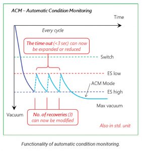 Developers achieved this by bundling several features under an energy-saving header. The base energy-saving function in a piCOMPACT SMART ejector automatically shuts off the energy supply when vacuum is no longer needed in a sealed or semisealed system. The shut-off level and hysteresis (how much the vacuum level can drop before restart) is fully adjustable. The function can save up to 95% of compressed air usage in a lifting cycle.
The energy-saving system (ES) combines with automatic level determination and automatically sets optimized ES shut-off and restart levels in every cycle based on actual conditions.
Automatic condition monitoring (ACM) turns off the ES function in case of significant leakage in the system to protect the valves from switching on and off rapidly and to prolong valve lifetime. A leakage warning output signal is available when ACM is triggered. The leakage warning is an important aid for preventive maintenance and increased uptime. If semiporous material such as cardboard or surface-leaking materials such as a bag of crisps are handled, more leakage in the system may be necessary to suite the application. In this case the ACM recover cycle can be modified accordingly.
Finally, adaptive pulse width modulation (A-PWM) reduces the power to the valves when they are in holding position and allows for full power when switching the valves to achieve a response as quickly as possible. The adaptive part allows for fluctuating voltage without impacting functionality. A-PWM significantly reduces power consumption, generates a lower temperature, increases robustness of the installation, and thereby extends the life of the gripping unit.
Digitizing vacuum generation for pick-and-place applications in the automotive industry, among others, helps realize the Industry 4.0 promises of more efficient equipment, systems, and processes. Making predictive maintenance feasible, the piCOMPACT23 SMART ensures high machine uptimes as it monitors environmental conditions that influence the system’s performance.
With an eye on the automotive industry with its high degree of automation and handling of large and heavy parts, the safety features increase operator safety and, for the first time, allow the deployment of compact-style ejectors without additional expensive supporting equipment or workarounds.
Taking growing trends toward collaboration between robots and humans into consideration, Piab is now working on minimizing the system size to fit ejectors that can integrate into specific vacuum cobot gripping solutions. Here the IO-Link plays an important role, while sensors can be included in the gripping unit directly. λ

