Traction Control Using Torque Divider
Controlling traction in hydraulic propel applications can be a slippery situation. Good traction demands all driving wheels take an equal share of propulsion loads, without slipping, scuffing, or cavitating. There are a wide variety of hydraulic propel circuits and products available to today’s vehicle designer, including both closed and open circuit pumps and motors. Economical series circuits are prone to cavitation, as inside and outside turning radii differ. Parallel circuits consume energy in the flow dividers and still require additional accommodation for differing wheel speeds. This article details the approach leading to the development of a multifunctional cartridge valve that divides torque between loads in a series circuit. It discusses the benefits of the new approach.
Closed-loop hydrostatic drives offer many advantages in propel applications. These high-power density drives are compact, and they allow vehicle designers much flexibility in component location and speed control.
There are many choices available when implementing a hydrostatic propel system. Finding a system that fits economically and performs well is a challenge that requires evaluating competing approaches. Important considerations are weight, size, flexibility, performance, cost of components, and economy of operation.
This article describes basic parallel and series drive circuit configurations to establish the challenges any hydraulic traction drive might experience. Load-balancing, traction control, and steering differential had particular impact on the development of the solution.
A Reason for Change
Traction circuits are possible with various plumbing configurations, and each has its own advantages and disadvantages. Driving over uneven terrain or in adverse conditions, such as mud, snow, and ice, offer the challenge of preventing wheel slippage when loads on each wheel can be different. Then there is the competing challenge of allowing wheels to turn at different speeds to accommodate steering geometry, while also ensuring they provide adequate and even tractive effort to the vehicle. Not the least consideration is providing a solution that fits a particular vehicle’s market economics. A quick look at the common drive circuit types allows us to look at the issues of each configuration and informs a balanced approach.
The Series Propel Circuit
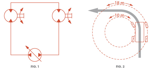
Series circuits, as implied, have a single path of flow through multiple motors. The series circuit ensures all motors turn, even when loads differ at each wheel. Pressure drop at each motor is additive in series circuits (Fig. 1).
Issues
Because pressure drops are additive in a series circuit, the inlet pressure at the upstream motor(s) can be very high. This can raise case pressures, stressing shaft seals and internal components. Motors with case drain can experience elevated flows when in upstream position.
In a traction circuit, all motors are in contact with the ground. This forms a semi-rigid connection: all motors want to turn at a similar speed. If the motors in the circuit have case drains, downstream motors can cavitate severely because of fluid exiting by the drain. A cavitating motor has negative inlet pressure and therefore does not contribute any tractive effort to the system.
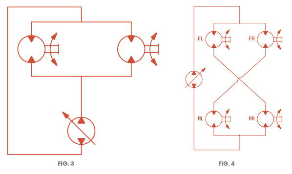
Cornering vehicles experience turning differential. The turning circles of all wheels are concentric, therefore the speeds aren’t equal. This can cause problems, such as cavitation or scuffing the surface (Fig. 2).
Parallel Circuits
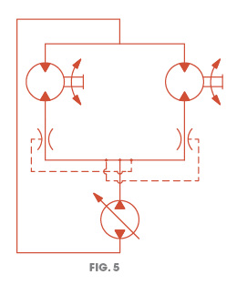
Parallel motor circuits split pump flow between multiple motors. Pressure in each circuit branch varies according to load. All branches of a parallel circuit share the total output flow. Flow in parallel circuits favors the circuit branch with the lowest pressure drop (Fig. 3).
Issues
This type of circuit only works well when all motors are evenly loaded. Any small difference in wheel traction easily leads to spin out, consuming all flow from the other branches. This is not a practical solution for traction control.
Series/Parallel Circuit (4-Wheel Drive)
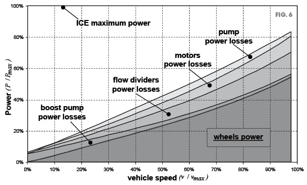
The series/parallel circuit is typically employed with opposite motors in series (FR+RL, RR+FL). This can balance tractive effort in the system simply because loss of traction is less likely to occur at opposite corners of the vehicle (Fig. 4).
Issues
This configuration is essentially two series circuits and two parallel circuits. As such, it has weaknesses of both approaches. It functions well as long as wheel loads and speeds are all well matched in all driving conditions. This may be an acceptable configuration for vehicles with articulated steering, where turning differential is not an issue.
Parallel Circuits with Flow Dividers
 By far the most common traction circuit employs parallel flow with divide/combiner valves. These valves are pressure-compensated flow controls that split a flow into two parallel branches. They also operate bi-directionally to combine two branches. Two metering spools operate together such that if pressure rises in one branch, the opposing leg is restricted. This ensures even division while compensating for pressure differences in the branches.
A circuit using flow dividers can ensure all wheels turn regardless of load differences. Being a parallel circuit, pressure drop is not additive, and it will not exhibit the cavitation problems when used with motors that have a case drain (Fig. 5).
Power Losses
Flow divider/combiner valves are restrictive metering devices. They operate more accurately with a higher pressure drop. This can contribute significant losses and heat to a traction drive. Pressure drop increases with flow. Fig. 6 illustrates that flow dividers contribute the highest parasitic loss of all components in a hydrostatic propulsion drive.1
Turning Differential
The flow divider/combiner valves in this type of circuit perform well at ensuring all wheels turn at the same rate. This circuit is unable to accommodate turning differential. The typical solution is to add a slip orifice that allows some flow to bypass the flow dividers. Flow through this orifice does no work, so therefore detracts from the system efficiency. It also represents a leak path for flow from a slipping wheel.
Differential Lock
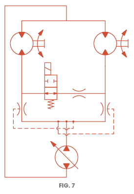 Vehicles with generally even wheel loading may operate acceptably in a circuit with an as-needed locking differential. The operator can activate a solenoid valve that locks in the flow dividers only when the vehicle gets stuck. From an operator’s perspective, a system that does not get stuck to begin with is desirable, but there is also added cost of the extra valve and circuitry to control it (Fig. 7).
The Challenge
To sum up, the issues in traction control are many, including
- Load balancing
- Wheel slippage
- Cavitation
- Steering differential
- Power losses
- Cost
A New Approach
Given the limitations of the traditional systems described, a new approach was needed to meet the conflicting needs. The system needed to allow motors to operate at different speeds, without slipping, and for each to take a fair share of the propulsion load.
The Secret is Pressure Control
We approached the propel circuit as a pressure control problem, rather than a flow control problem. While flow divider/combiners keep flow constant regardless of changing circuit pressures, a pressure reducing/relieving concept can keep pressure constant regardless of changing flow requirements. The idea is to balance the torque at all the wheels. Using a pressure divider network, we can sense half the pressure in the circuit and use that to pilot the reducing/relieving valve. The series circuit keeps both motors turning to eliminate wheel slip, but the torque divider keeps the pressure drop equal so both motors are sharing the load.
 The pressure divider network uses two equal orifices to halve the pressure across the series circuit. Varying the orifice ratio, alternate torque sharing combinations are possible. This is useful when you have motors or wheels of different sizes, or differing loads from front to back. If needed, a small flow regulator, in line with the torque divider, can improve performance in very low traction environments, such as driving on ice.
The valve only passes a fraction of the total drive circuit flow. It is responsible for the difference in flow only. This makes it an energy saver when compared to flow divider/combiner valves, which operate best at a pressure drop of 10-20 bar (150 to 300 psi) and have to pass the total drive circuit flow.
The Torque Divider
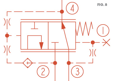
The HTD10-40 is a pressure reducing/relieving valve that adjusts its setting to half the pressure across ports 2 and 4. It allows flow from 3 to 4 or 2 to 3 as needed to balance the spool. The spool is balanced when the pressure at 3 is half the pressure between 2 and 4 (Fig. 8). Alternate ratios are possible.
Features
- Size: 10-size, 4-ported cavity
- Operating pressure: 5000 psi / 350 bar continuous (6000 psi / 420 bar intermittent)
- Flow rating: 60 lpm / 15 gpm
- Accuracy: 90%
- Pilot flow screened to protect the pressure divider from contamination
Performance
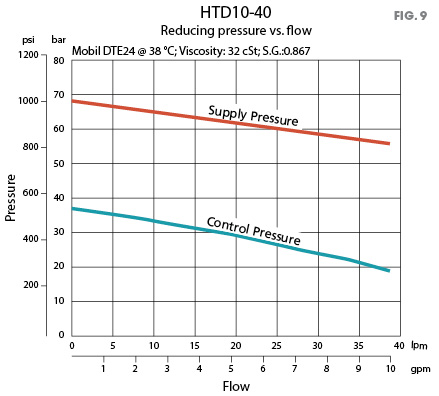
Once the valve was developed, laboratory testing validated its operation to specification. It performed very well. The graph in Fig. 9 shows pressure at port 3 remains half of the pressure seen across 2 and 4.
Circuit
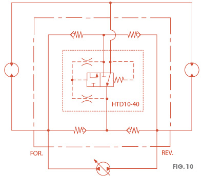 The HTD10-40 is positioned at the midpoint of two series motors. The check valves resolve high/low loop pressure for bi-directional operation (Fig. 10).
Advantages
This is a new solution to an old problem. It is another tool in the kit for system designers. It isn’t for every propel application, but where it fits, it fits well. Here are some of the advantages:
- All hydraulic solution—no sensors or controllers
- No electronic development, programming, or tuning
- Simplified circuit—easy service and troubleshooting
- Optimizing flow rating—sized only for the turning differential flow
- Good in low-traction applications
- Efficient—less wasted heat generation
- Economical—right-sized components, low valve count
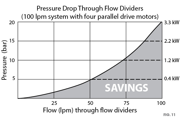
The graph in Fig. 11 represents a system with four parallel drive motors (and three 12-size flow dividers) consuming 290 psi / 20 bar at 100 lpm (3.3 kW). The graph shows the approximate kW ratings at a given rated flow when applying the HTD10-40 instead of a less efficient flow divider.
REFERENCES
1A. Vacca, G. Franzoni, F. Bonati, “An inclusive, system-oriented approach for the study and the design of hydrostatic transmissions: the case of an articulated boom lift,” SAE International, 2008-01-2686, p. 5.
By HydraForce, Inc.’s Travis Schmidt, CFPS; Scott Parker, CFPS; and Ben Dupre
For more information: Travis Schmidt, CFPS, is application engineering manager – Asia Pacific, Scott Parker, CFPS, is an application engineer, and Ben Dupre is senior technical writer. This article is based on a white paper presented at KSFC Fall Conference on Drive and Control, October 2015, in Busan, South Korea. Contact HydraForce at www.hydraforce.com.
Share this information.
Related Posts


One thought on “Traction Control Using Torque Divider”
Leave a Reply
Sponsor

Sponsors
Contact your HydraForce application engineer or technical service representative for information or application assistance with the HTD10-40 torque divider.