Graphical Standard 1219
By Gary Baumgardner, principle engineer at Parker Hannifin Corp., TC 131 chairman
We use or are guided by graphical symbols every day of our lives. Stop signs are standardized hexagonal graphical symbols indicating when you need to stop and yield to oncoming traffic. School zone signs, caution signs, and no-passing-zone signs all have standardized shapes and give us graphical indications of pertinent information for our day-to-day activities. Standardization of graphical symbols is necessary to make graphical symbols universally understood. Today’s family of ISO 1219 graphical standards provides universally understood graphical symbols that are used in the fluid power industry and understood globally.
The use of graphical symbols goes back to prehistoric times. Cave art conveys graphical information for what early man found important to depict and preserve. Egyptian hieroglyphics are basically a form of graphical communication. The ability to read and understand the meaning of the Egyptian hieroglyphics was lost over time, and it wasn’t until the Rosetta Stone was discovered by soldiers attached to Napoleon’s army and used to help decipher the Egyptian hieroglyphics that the meanings of these symbols was understood. Graphical standards like ISO 1219 can be thought of as a form of a “Rosetta Stone” for the understanding and use of fluid power graphical symbols.
I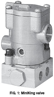 SO standard 1219 was first published in 1976, but it was not the first attempt to define and codify industrial fluid power symbols. Standardized electrical symbols were first published in 1947 by JIC (Joint Industrial Council). JIC hydraulic graphical symbol standards were then published in 1948; pneumatic standards followed in 1950. In 1954, the American Standards Association (ASA) developed a joint standard for hydraulic and pneumatic graphical symbols (ASA Y32.10-1958). ISO 1219 was first published as a recommendation in 1970, and the first official publication of ISO 1219 as a standard took place in 1976.
It is often said that “a picture is worth a thousand words,” and this is definitely true of graphical symbols. Graphical symbols can convey clear meaning for a system component with only one symbol, whereas verbiage to convey the same idea may take a paragraph or more to explain—and then not be universally understood. One of our young engineers was asked to prepare a training narrative on some of our standard products and was having trouble understanding the inner workings of our MiniKing valve, one of our older 4-ported, 4-way valves (Fig. 1).
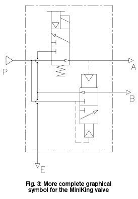
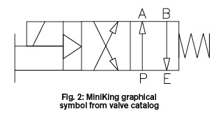 The catalog description was “4-way, two-position, solenoid-operated, spring return valve with manual override” (Fig. 2). The catalog gave a simplified schematic for the MiniKing valve, but the function of the valve was not well understood from the catalog information. We discussed the mechanism, but still the function was not apparent to the new engineer. To depict the function more clearly, I made a more detailed diagram of the valve’s internal function. From this expanded diagram, the inner workings of the valve became obvious (Fig. 3).
The MiniKing is really two 3-way valves working together to provide a 4-ported, 4-way valve function. With the solenoid de-energized, air flows from the inlet to port A. Port B is open to exhaust. When the solenoid is energized, air flow from port A is redirected to the common exhaust port of the MiniKing. The pilot signal to the internal air-piloted 3-way valve is lost, allowing the air-piloted 3-way valve to shift, pressurizing the B port of the MiniKing valve. It is not uncommon to use two 3-way valves to create a 4-way valve function, but in this case it was not immediately apparent from looking at the valve symbol or the valve detail drawing how this was accomplished.
The current version of ISO 1219 is published in three parts:
- ISO 1219-1 Part 1: Graphical symbols for conventional use and data-processing applications
- ISO 1219-2 Part 2: Circuit diagrams
- ISO 1219-3 Part 3: Symbol modules and connected symbols in circuit diagrams
 ISO standards are systematically reviewed every five years. The current version of ISO 1219-1 was last revised and republished in 2012, and it will be again up for review in 2017.
Fluid power graphic symbols will continue to evolve, but their utility and understandability have not lost their meaning over time. Today’s young users, with a minimum amount of exposure to ISO graphical standards, can readily view and understand the meaning of fluid power components and the function of system schematics using these symbols. It makes little difference if you are looking at symbols or schematics made using the most up-to-date software and the latest version of ISO 1219 or looking at schematics drawn 50 years ago. The message conveyed by the symbols clearly depicts the function of the component or system.
Standardized symbols also transcend language barriers. Users in Europe, Asia, or the Americas can look at individual symbols used in complex system schematics and understand the basic function of the components without having to understand a foreign language. Graphical symbols go beyond language to give universal understanding of intended function.
The next issue of Fluid Power Journal will contain another article in our series focusing on ISO standards awareness.
ISO Resources
The NFPA Standards Locator: www.nfpa.com/standardization/findstandard.aspx
“Why Standardize?” Find more information at www.nfpa.com/standardization/whystandardize.aspx
Interested in joining a TAG committee? Visit www.nfpa.com/standardization/standardscommittee.aspx
Contact Gary Baumgardner, current TC 131 chairman, at gbaumgardner@parker.com or email John Berninger at jberninger@parker.com. Learn more about NFPA and ISO standards at www.nfpa.com/standards.
Share this information.
Related Posts


Sponsor

Sponsors