How Clean Is Your Hydraulic Fluid?
Of all the oil-lubricated assets found in industrial plants, hydraulic systems are by far the most sensitive to contamination. Put simply: kept clean, they should run reliably; allowed to get dirty, and it’s likely that problems will occur. The reason for this sensitivity stems from the unique components used in hydraulic systems. From pumps to valves, cylinders to motors, clearances are tight, making even the smallest particle or water droplet a potential problem.
The design of hydraulic systems is, of course, many and varied and beyond the scope of this article, but they all share some common features with respect to the hydraulic fluid power system. First is the reservoir. Designed well, the hydraulic reservoir can aid in contamination control by allowing contaminants to either drop to the bottom of the tank or be removed by supplemental kidney-loop filtration that may be installed. By contrast, poor design, which might include too small a tank for the required fluid flow or suction, and return lines that are too close without adequate baffling between them, can cause problems to occur.
Next up is the pump. For lower-pressure systems where gear pumps are commonplace, contamination control is not as much of an issue since most gear pumps are reasonably forgiving with respect to contamination. By contrast, vane and piston pumps—particularly where variable volume pumping is required—have very tight clearances and by inference a much lower tolerance to contaminants.
Finally, we need to consider the flow control valves. Again, the sensitivity of valves to contamination can vary widely. Simpler systems where check valves or directional valves are used are typically far less prone to contamination-induced failure compared to more complex servo-controlled systems, which are very sensitive to contamination, particularly where valve dwell times are long.
Developing a Contamination Control Strategy
For any plant that relies on hydraulics, developing a comprehensive contamination control strategy should be high on the priority list. This is a fairly simple three-step process:
- Develop contamination control targets based on system design.
- Take action to meet or exceed contamination control targets.
- Use oil analysis to make sure target cleanliness levels are maintained.
Let’s look at the each of the three steps in more detail.
1. Developing Cleanliness Targets
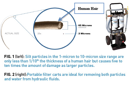
For the purpose of this article, we’ll consider the two primary contaminants found in most plants: particles and moisture. However, a similar three-step approach can and should be used for other contaminations, such as air or heat, both of which can have a deleterious effect on hydraulic systems. For particle contamination, our primary concern needs to be silt-sized particles in the 1-micron to 10-micron size range. While small in nature—less that 1/10th the thickness of a human hair—3-micron silt-sized particles, which are no bigger than a red blood cell, are as much as five to ten times more likely to induce a failure. The reason for this lies in the fact that many filters are not designed to remove such small particles, coupled with the fact that dynamic clearances (the separation between moving parts under operating load, speed, and temperature) in pumps and valves are typically in the 1-micron to 5-micron size range.
Particle contamination is usually expressed according to the ISO 4406:99 standard. This standard reports particle concentrations in hydraulic fluids in three size ranges: particle >4 microns, particles >6 microns, and particles >14 microns. For those unfamiliar with this standard, a number of excellent articles are available online that explain the standard.1
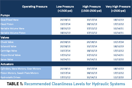
Based on the ISO 4406:99 standard, Table 1 shows recommended target cleanliness levels for different types of hydraulic systems. For highly critical systems, the target cleanliness levels detailed in Table 1 should be lowered by one to two ISO codes (i.e. for a highly critical servo-controlled system running at 3,000 psi, we would lower the target from ISO 15/13/10 as shown in Table 1 to ISO 14/12/9).
Aside from particle contamination, water is the second most insidious contaminant found in hydraulics. Present in most fluids even in the most pristine environments, water can increase failure rates 10-20 fold depending on circumstance. Water causes problems in a number of ways: first, any iron or steel surface in contact with water will start to rust. This can induce premature failure due to corrosion, as well as introduce rust particles into the fluid. Second, water is very different to most hydraulic fluids in that changes in pressure and temperature can readily induce a phase change. While water may be a liquid under atmospheric pressure inside the reservoir, on the suction side of a hydraulic pump the lower pressure can cause water to vaporize even at relatively low temperatures. These vapor-filled bubbles will continue to grow until they reach an area of high pressure (e.g. on the discharge side of the pump) when the bubble suddenly and violently collapses. The intense pressures generated by such microscopic implosion events can cause damage to pumps and valves—an effect referred to as “vaporous cavitation.”2 Water also helps pull oil degradation byproducts out of solution, which can cause sticky-resinous deposits to form. When these deposits accumulate in the clearances of valves, they can cause small particles to become trapped, further increasing the system’s sensitivity to particle contamination.
So how much water is too much? To a large extent the answer depends on the type, the age of the fluid, and the operating temperature. The reason for this lies in the form that water takes in lubricants and hydraulic fluids. Most fluids will hold a certain amount of water in the dissolved phase. For the most part, as long as the water remains dissolved, cavitation and corrosion will not occur. However, as soon the water comes out of solution and becomes free or emulsified, water becomes a very real concern. While highly temperature dependent, the saturation point of most conventional hydraulic fluids—the point at which water starts to come out of solution—is in the 100-200 ppm range (0.01-0.02%). Below these levels, most hydraulic systems should be relatively free of water-induced failures.
2. Excluding Particles and Moisture
Once cleanliness targets have been established, the next step is to take measures to meet the targets. To do this we need to focus on two areas: contamination exclusions and contamination removal. Contamination exclusion focuses on making sure that particles and moisture never make it into the system in the first place, while removal requires the use of filters and other systems to remove them from within the system. Our efforts should always start with exclusion since it costs as much as 10 to 15 times more to remove contaminants than to keep them out from the start.
Contamination exclusion requires a holistic focus on all steps of the process of lubrication—from receipt, storage, handling, dispensing, and finally use of the lubricant within the system. Perhaps the first place to start is with the storage, handling, and dispensing of new oils and recognition that most new oils coming into the plant are too dirty for immediate use without pre-filtration. Even new oil in a barrel that has yet to be opened will show particle concentrations in the 18/16/13-191/17/14 range and as much as 400-500 ppm of water, which is too dirty and wet for most hydraulic applications.
Because of this, the rule of thumb is that all new hydraulic fluids should be pre-filtered at least five times prior to use. For most applications, using a 3-micron filter complete with a permanent or portable kidney-loop filtration system is sufficient. For highly critical applications where lower particle counts are required, we may even need to go down to a 1-micron filter.
To remove moisture, we may also need to use a polymeric water-removing element. These elements use a water-absorbent polymer (similar to baby diapers) that absorbs water and retains it within the filter. Both water and particle removal can be achieved simultaneously with two filter heads in series—first using a water-removal element followed by a particle-removal element (Fig. 2).
The next step is to transfer oil from storage to the system. To do this, common practice is to remove the oil fill port on the reservoir and transfer the fluid using a transfer pump. However, in doing so we expose the system to airborne contaminants, which can enter through the open fill port. A better approach is to install quick connects so the system can be filled non-intrusively using the same filter transfer cart shown in Fig. 2.
Once inside the reservoir, our job is not done yet. All systems breathe, so even if there is no net flow of oil into or out of the reservoir, changes in ambient and operating temperatures ensure that there will always be air exchange from the outside in and vice-versa. For many hydraulic systems, of course, there’s a large exchange of air with every cycle: as fluid leaves the reservoir—for example, as a rod extends out from the cylinder—air needs to flow into the system to compensate for the volumetric change in fluid level in the tank. When this occurs, many hydraulic systems suck in vast quantities of dirty, contaminated plant air. Despite this, many hydraulic systems are still designed with inadequate combination breather and filler caps, such as that shown in Fig. 3. Within this fill cap/vent, particle exclusion is by means of a wire mesh, steel wool, or foam—none of which exclude silt-sized particles—while water exclusion is non-existent. Where present, standard breather filler caps should be replaced with a combination manifold (Fig. 3), which permits the use of a high-efficiency particle and desiccant (water-removal) element, as well as quick connects for oil fill and sample valve for oil sampling. When selecting a desiccant breather, care must be exercised to ensure that airflow rates through the breathers match the maximum anticipated oil flow rate, but this can easily be achieved for even the largest systems.
3. Measuring contamination levels
The final step in the process requires the use of oil analysis to validate that our contamination control measures are having the desired effect. For hydraulics, measuring the degree of contamination in the oil should be commonplace. For particle contamination, particle counting using the ISO 4406:99 standard outlined above should be used, while for water content, % or ppm of water should be reported using the Karl Fischer water test (ASTM D6304). However, oil analysis is only as good as the sample that’s taken. Wherever possible, samples should be taken on the return line from actuators. In some cases, this may mean multiple samples from the same system where separate return lines are in place. For hydraulic systems without adequate return-line flow, samples can be taken from the reservoir but will be less indicative of what’s happening in the rest of the system.
Summary
Hydraulic system reliability is inextricably linked to contamination levels. Kept clean and dry, well-designed hydraulic systems should be relatively trouble-free. Allowed to get dirty, they can become unreliable and troublesome. Contamination control is possible, even in the harshest environments. With just a few basic concepts and a simple three-step process, controlling contaminants can be as easy as 1-2-3!
REFERENCES
1How Important is the ISO Cleanliness Code in Oil Analysis? Matt Spurlock, Machinery Lubrication Magazine May-June 2012
2Proactive Maintenance for Mechanical Systems, E. C. Fitch, FES Inc., 1992
For more information: Mark Barnes, vice president of reliability services, has been an active consultant and educator in the maintenance and reliability field for over 17 years and has worked with clients around the world to design and implement lubrication improvement plans. Contact him at mark.barnes@descase.com.
Share this information.


Sponsor

Sponsors
2 thoughts on “How Clean Is Your Hydraulic Fluid?”