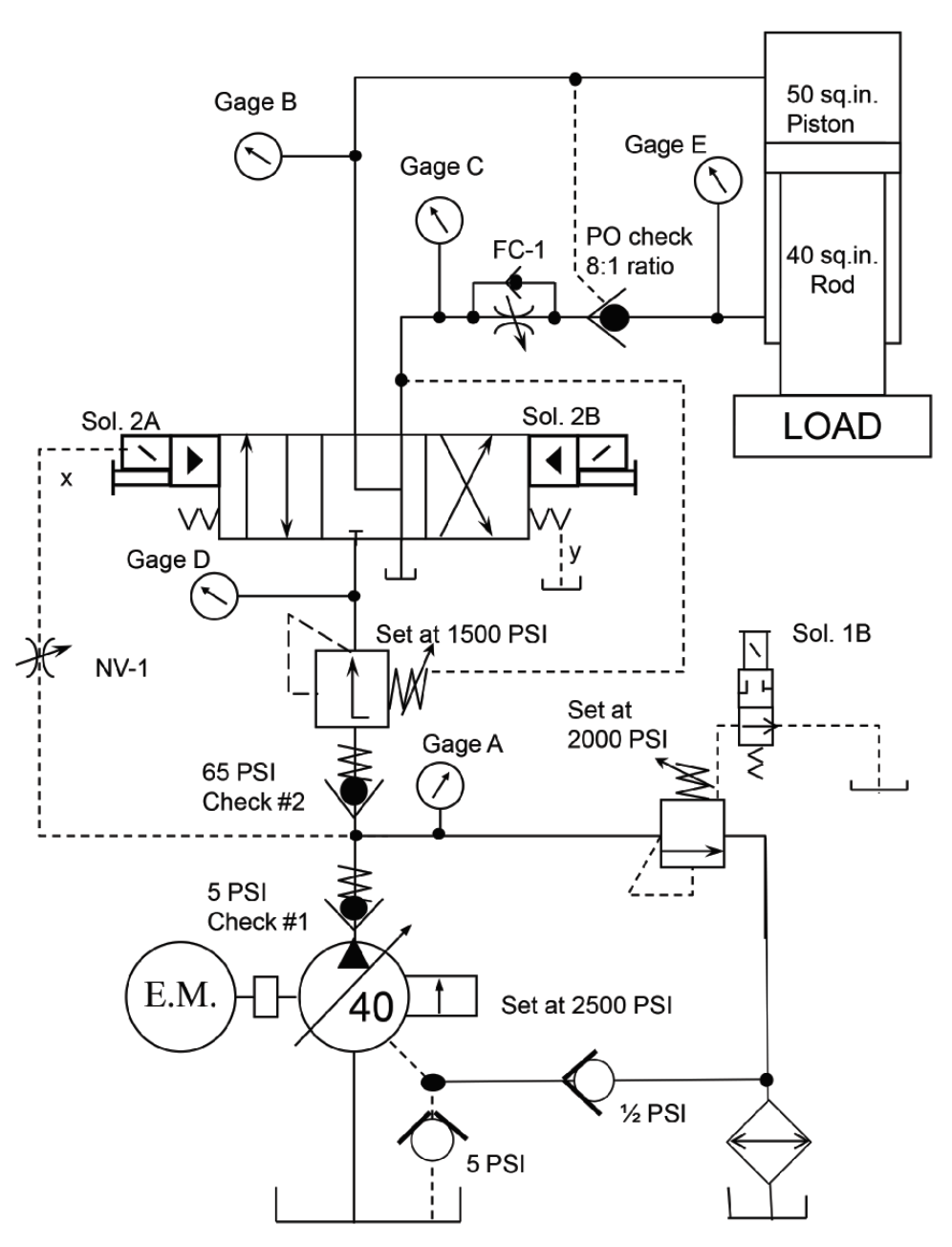
Ram Does Not Retract on a Forming Press

By Robert Sheaf, CFPAI/AJPP, CFPE, CFPS, CFPECS, CFPMT, CFPMIP, CFPMMH, CFPMIH, CFPMM, CFC Industrial Training
The circuit shown here was a press I designed some years ago. A problem developed with the ram not returning after forming a steel truck bumper. The pressure-reducing valve that was leaking out of the pressure adjustment screw was replaced with one from the company’s stock. It was the D08 module located under the main directional valve.
The pressure-reducing valve setting was adjusted to accommodate the different bumper designs. If the pressure was too high when pressing, the ram die would cause the material to tear. Each bumper design had a specific tonnage that would work well in the forming process.
When the new valve was set to pressures below 1,200 psi, the ram could not be pulled off the formed bumper. The operator would have to increase the pressure on the reducing valve to about 1,700 psi to get the ram to retract. Once off the formed bumper, the press would retract with less than 900 psi.
What could be the solution?
See the Solution
Robert Sheaf has more than 45 years troubleshooting, training, and consulting in the fluid power field. Email rjsheaf@cfc-solar.com or visit his website at www.cfcindustrialtraining.com. Visit www.fluidpowerjournal.com to view previous problems.


