Excessive Pressure Drop on a Test Stand
![]() A hydraulic distributor designed and built a test stand with various sizes of sub-plates for mounting and testing pressure and directional valves. There were 10 sub-plates in all. They had a piston pump with a pressure compensator set at 4,000 psi and a volume adjustment with a range of 2 to 10 gpm of flow. A safety relief was used and set at 4,200 psi, as well as a kidney loop/cooling unit. The unit also had a flow meter on the main tank return line.
A hydraulic distributor designed and built a test stand with various sizes of sub-plates for mounting and testing pressure and directional valves. There were 10 sub-plates in all. They had a piston pump with a pressure compensator set at 4,000 psi and a volume adjustment with a range of 2 to 10 gpm of flow. A safety relief was used and set at 4,200 psi, as well as a kidney loop/cooling unit. The unit also had a flow meter on the main tank return line.
The pump pressure and return connections were two-bar type manifolds with ½” SAE #8 quick disconnects, and each sub-plate also had ½” quick disconnects (QD) for hose connections. Sub-plates needing a drain and/or pilot pressure connections used ¼” QDs and hoses. They had a nicely designed hose rack for unused hose to drain. The QDs were the flat-face type to reduce the spillage typical of connecting and removing hose on a test stand.
With this arrangement, they intended to plumb up the valve to be tested to an actuator. There was a motor and a single rod cylinder for completing the setup. In general, it was a fairly nice valve test stand.
To test out the stand for performance, they mounted a new ISO-3 (D02) directional valve rated at 14 gpm with a 72-psi pressure drop. It was mounted, and the hoses with the QDs were attached to the pressure and tank manifolds and to the motor. The valve was a blocked-centered, 3-position, 4-way with solenoids on both ends.
With the directional valve in the blocked center position, they set the safety relief valve and adjusted the compensator. Next, they wanted to set the flow on the pump to its full flow of 10 gpm. They connected an electrical cord to one of the solenoids, shifting it so the motor would run freely and they would see the return flow through the flow meter. As they were increasing the flow, the pump pressure started climbing beyond the 72-psi pressure drop expected for 14 gpm, and once they had all 10-gpm pump flow going back to the tank, the pump pressure was 600 psi.
They rightfully determined that there must be a restriction somewhere or that the motor required a much higher-pressure drop than expected. To check this, they disconnected the motor and looped one of the hoses to connect the A and B ports on the ISO-3 sub-plate. They still had the high-pressure drop. They tried another new valve off the shelf, and it didn’t help. They inspected the sub-plate to find all the drilled holes and fittings were drilled properly. They thought that maybe a QD was malfunctioning, so they replaced all the QDs and at the same time checked all the ½” hoses for obstructions. None were found. They did notice that one end of all the ½” hoses had a male SAE O-ring thread, and the other end used a 37° tube union with an O-ring to connect to the QD. The hose had a female 37° that the other end of the union fit into. The 37° tube threads are identical to the SAE O-ring, and a lot of shops (including ours) just add the #908 O-ring to convert it to a SAE #8 connection.
They had a hose with female 37° ends on both ends, so they looped the pressure and tank manifold connections together, and the pressure was less than 20 psi. They eliminated the pump outlet to the manifold plumbing.
Any idea what could be causing the problem?
See the Solution
Share this information.
Related Posts
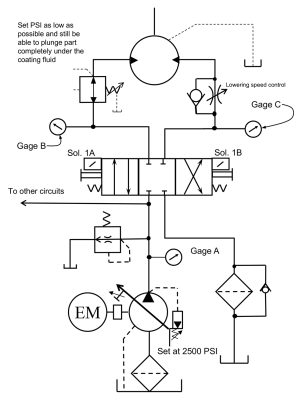
Figure It Out: Extractor Motor Reverse Speed Rises to an Unexpected Creep

Directional Valve Seals Failing
Overheating on a Large Forging Press
Main relief valve keeps coming apart in manifold.
Clamp and Drill Circuit Will Not Release the Part
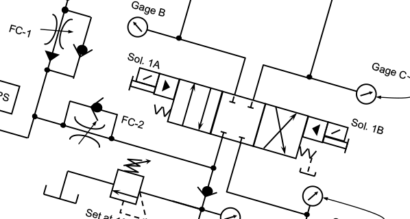
Figure It Out: Loud Noise Heard When Shutting Off a Hydraulic System
4 thoughts on “Excessive Pressure Drop on a Test Stand”
Leave a Reply
Sponsor

Sponsors
Just curious. what is a “two-bar type manifold?”
Not sure if this is referring to to 2 solid steel bars machined to form a comon rail manifold
I think your problem is that you are measuring flow and trying to develop pressure. With the motor running “freely” there’s no load to speak of so the system is developing enough pressure to do that work. The only way get the pressure to rise will be to either put a load on the motor or restrict the outlet flow. Remember the basics flow is speed and pressure is work. You won’t see full pressure until there’s either a lot of work being done or almost no flow.
I would go for the QDs every time
Esp the flat seal type, horribly restrictive
Cheers
Australia