Reaching New Heights in Load Holding for Cranes
By Steve Weber, Engineering Team, Sun Hydraulics
Efficient, effective load holding is not easy. But you can improve your results and achieve counterbalance in almost every application if you apply an informed counterbalance valve selection in a smart circuit design. Two case studies involving cranes demonstrate the necessity of good counterbalance valve selection and the importance of smart circuit design for the best performance and stability.
Case study 1: The Federated construction crane
A load-holding challenge began with the collapse of a crane at a New York City construction site. As a result of the collapse, city building inspectors changed their inspection process at active construction projects with cranes. It would now include looking for evidence that the counterbalance valve had been adjusted after leaving the factory, which would demonstrate to the inspector that the valve had been tuned to the application. If there was no obvious way to show that there was a post-factory setting, the load-holding valve had to be replaced.
The chief engineer at Federated Crane Company contacted Sun Hydraulics and asked what options Sun could offer to help meet this new requirement. During the discussion, the conversation expanded to include the real challenge – improving the performance of the winch on their cranes.
Federated Crane’s equipment mounts to the side of a building under construction and climbs the outside of the building as the skyscraper expands upward. A track is mounted on the building and a pony motor powers the hydraulic system that moves the crane up the side of the building. These cranes are used to deliver materials such as concrete and rebar to the floors under construction. As a result, the winch control has to account for a 1000-foot payout of wire cable used to move materials up to the active floors.
Federated’s cranes had a Sun counterbalance valve installed on the winch circuit with a standard adjust screw. The engineer needed to replace the counterbalance valve with the standard adjust screw in the winch circuit with something that would satisfy the inspector’s requirement of a visible sign that the valve setting had been adjusted outside the factory. That was the easy part. The challenge was in his request to improve the performance of the winch.
The challenge. At that time, Federated Crane was working on the reconstruction of the World Trade Center, the tallest building in the U.S. and the sixth tallest in the world. As these cranes make their way up the building, that 1000-foot payout acts like a large spring-mass-damper system but with little dampening. In a winch circuit with a counterbalance, there is an inverse relationship of a lightly loaded hook needing higher system pressure to pay out. And with the long lengths of wire rope acting as a damper system, it makes stability particularly challenging.
Instability comes from the counterbalance valve being piloted too far open, which allows the actuator to overrun the pump, causing the system and pilot pressure to drop. As a result, the counterbalance valve suddenly closes. When system pressure and pilot pressure recover, the counterbalance valve reopens. This repeating cycle of opening and closing is often called chattering and can occur in both motor and cylinder applications. Chattering is a familiar sound to hydraulics engineers working on load-holding solutions.
In the Federated Crane application, smooth acceleration and deceleration of the load was critical. Without it, the long length of wire rope acted as a spring, allowing the winch motor to briefly overrun the pump, starting that cycle of instability and chatter. Performance of the winch was at times unstable and not smooth. The company’s chief engineer reported that when the hook was lightly loaded or had no load, stability was worse than when the hook was heavily loaded.
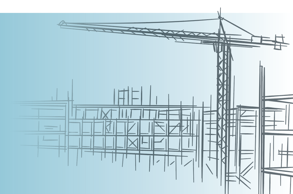
Figure 1 shows a typical open loop motor circuit in which the counterbalance valve acts as a brake for the motor driving the winch. The Federated Crane solution was a closed loop hydrostatic motor driving the winch. Therefore, heat generation was a prime consideration when deciding alternatives to improve performance. More heat could require more oil to be bled from the closed loop system for cooling. This might require a larger charge pump to replenish the hot oil that bleeds off for cooling.
The solution. This is where an informed counterbalance valve selection makes a difference. Sun recommended a load-control style counterbalance valve because it is hydraulically dampened internally and offers superior control resolution. The control resolution is improved by offering low-flow and high-flow modulation in the same valve. Additionally, it is a poppet valve, providing extremely low leakage for use as a counterbalance valve. But once the poppet leaves its seat, it acts like a spool valve to improve control resolution.
Pilot line dampening with an orifice is commonly included in the control circuit, which can sometimes create issues for a winch motor. A simple orifice dampens the pilot flow into the valve to slow the valve opening, but it also decreases the flow of pilot oil from the valve. This can lead to the motor overrunning the pump and cavitating. With an open loop winch motor circuit, regaining control of load might not happen, at least not until the load hits the ground, which for almost all applications is too late.
A smarter circuit design includes an orifice with a bypass check. This valve dampens the pilot flow into the valve to slow the opening, and the check valve allows the pilot flow out unrestricted to allow the counterbalance valve to close and prevent an overrunning load. Additional dampening is sometimes possible internal to the valve, making use of a similar concept to further dampen the valve opening but not slow the valve closing.
For the Federated Crane application, we combined the Sun load-control counterbalance valve with the internal dampening and pilot orifice in the new circuit with a bypass check valve and installed the resulting solution on the Federated crane. The result significantly improved stability compared to the original counterbalance valve. The chief engineer noted that the winch worked better than it ever had.
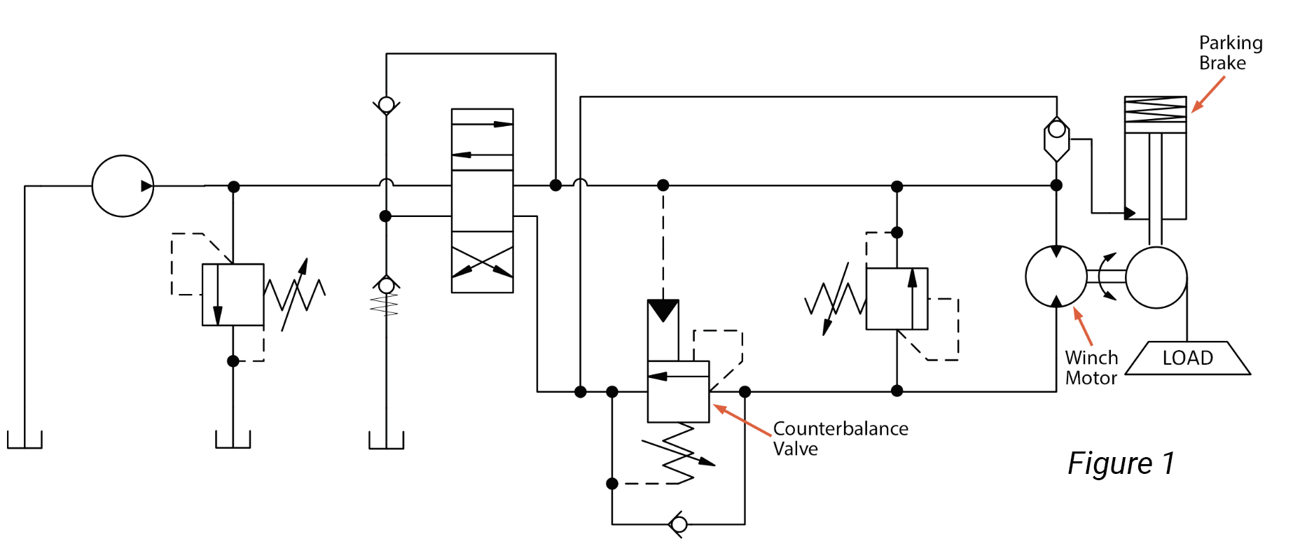
But why stop there? To further improve stability, a small accumulator was added to the pilot line. The schematic in figure 2 shows this modification on the typical open loop motor circuit. The small accumulator further smooths the pressure pulsations in the pilot resulting from the highly excitable spring-mass-damper created. The result of using an accumulator in the counterbalance pilot was, as one Sun engineer put it, “like a magic carpet ride.” After the final changes, the feedback from the Federated Crane operator was that the winch was stable in all conditions. Problem solved.
Case study 2: A truck-mounted crane
Truck-mounted cranes offer a different set of load-holding challenges. These machines are commonly used to deliver materials to a construction site. For this particular application, the customer already had a solution in place that was expensive, but they were experiencing long lead times. At the same time, the customer was looking for improved control resolution for safer, more precise movement of materials from the truck.
The key to this solution also included choosing the right valve and applying it in a smart circuit. Since the customer was using a balanced load-control valve, we decided to stay with that approach. With a balanced load-control valve, system pressure does not need to increase for a lightly loaded crane hook. However, the balanced load-control valve does not provide thermal relief protection. A separate relief must be built into the circuit. Even the reduced system pressure present that is used to pilot the balanced load-control valve open can still be too high, causing stability issues from an overrunning load. One way to deal with this issue is to use an orifice divider to reduce pilot pressure.
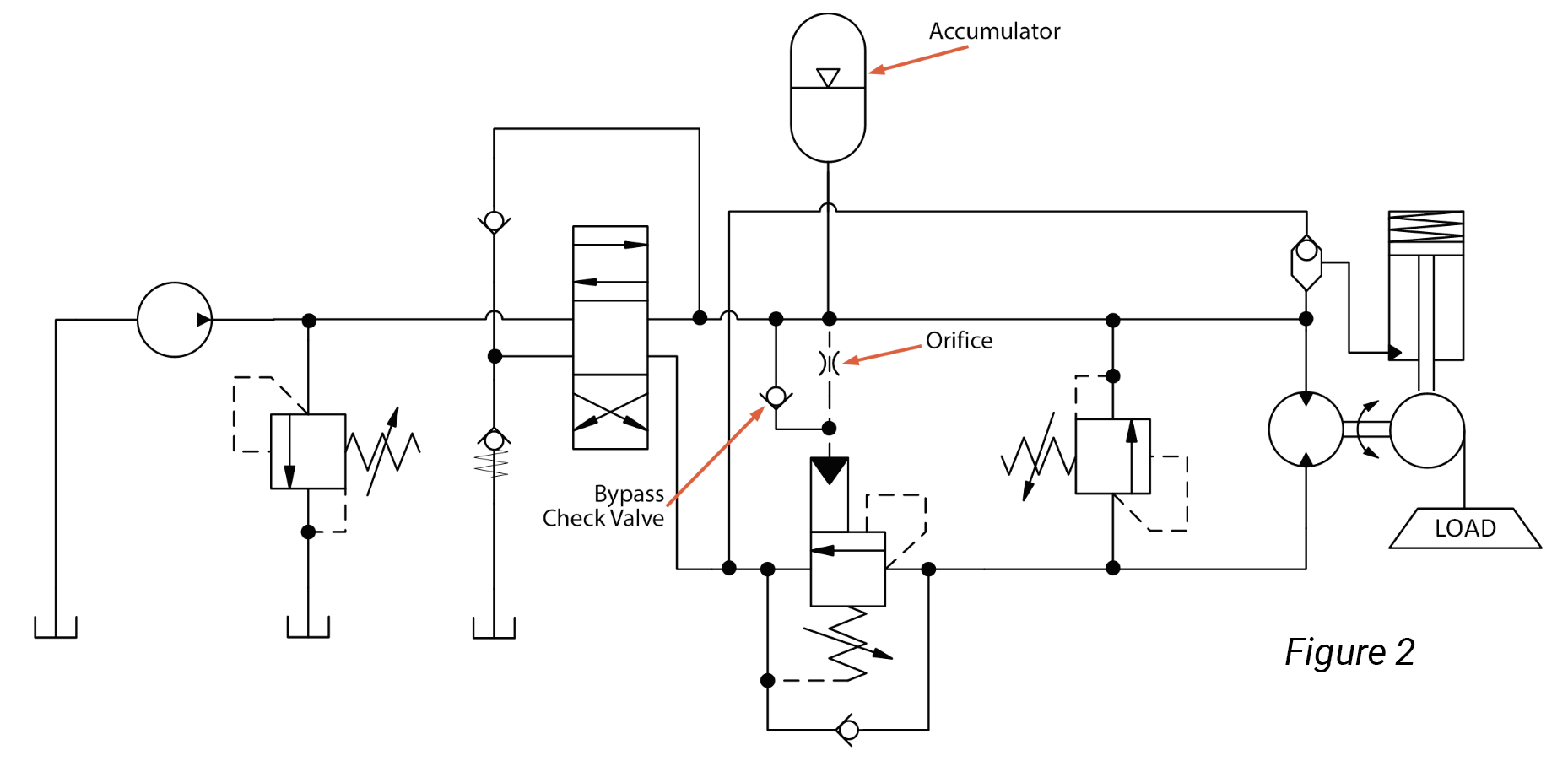
The challenge. Balanced load-control valves are attractive because the inverse relationship of pilot pressure needed to open the valve, which is higher for lighter loads, is replaced by a fixed pilot pressure required to open the valve regardless of the load pressure. However, in the traditional cross-piloted application where the cylinder piston-side counterbalance is piloted off the cylinder rod side or vice versa, the pilot pressure can end up being too high. The typical schematic is shown in figure 3. This sets up the actuator for an overrunning load condition that leads to the instability. In this situation, the valve over opens, the load overruns the pump supply, the pilot pressure collapses, and the valve closes. When the pressure recovers as the pump catches up, the valve is piloted open again, and the whole cycle repeats itself.
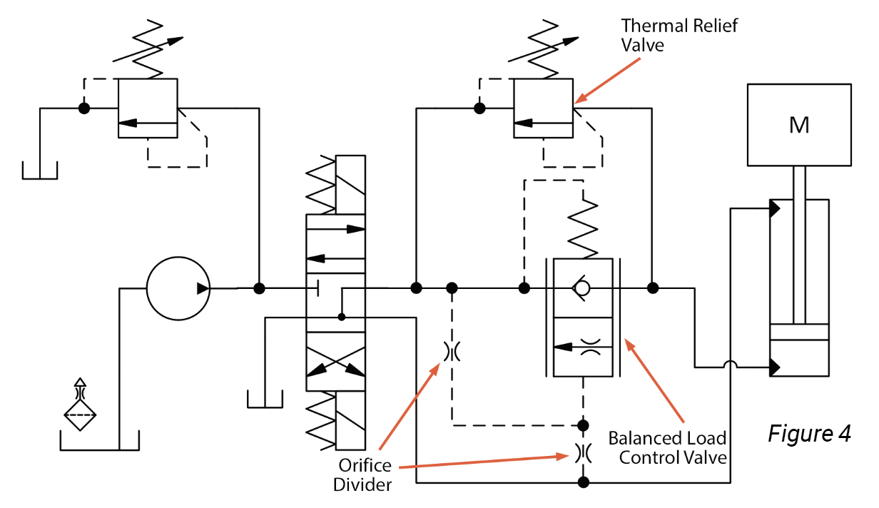
The solution. The use of an orifice divider can potentially solve the issue of too much pilot pressure on a balanced load-control valve that leads to an overrunning load and instability. The orifice divider acts to reduce the pilot pressure on the valve by bleeding some pilot flow off while restricting the flow into the pilot, functioning much like a voltage divider in an electrical circuit. Since the balanced load-control valve does not offer relief protection, a separate thermal relief should be added at a minimum. It is important that this relief valve is a poppet-style valve to reduce leakage on the load-holding ports. Using needle valves instead of fixed orifices can allow for tuning, but this runs the risk of allowing the effective orifice sizes to be tuned small enough that the valve closing is too slow, resulting in a cavitating actuator. However, it can be useful when prototyping. And users should consider using a bypass check on the pilot inlet orifice to allow the counterbalance valve to close as fast as it needs to. Figure 4 gives an example circuit.
Different applications may need additions to the basic load-holding circuit to stabilize the load-holding valve, as the Federated Crane application demonstrated with the long payout of wire cable. In the example of the truck-mounted crane, the situation demanded a valve that can provide precise control resolution, which means adding the orifice divider to keep the pilot pressure in the range the valve requires while preventing an overrunning load condition.
Share this information.
Related Posts


Sponsor

Sponsors