Recognizing Misaligned Cylinders
Misalignment of a cylinder occurs when the load is not applied along the centerline of the rod. Many applications have a small amount of inherent misalignment because of clearance requirements due to cylinder size. It travels through an arc or in parallel to a single support guide. Most cylinder misalignment problems occur when the rod is extending. As the rod retracts, the cylinder tends to pull on the centerline of the rod, even when the load is misaligned.
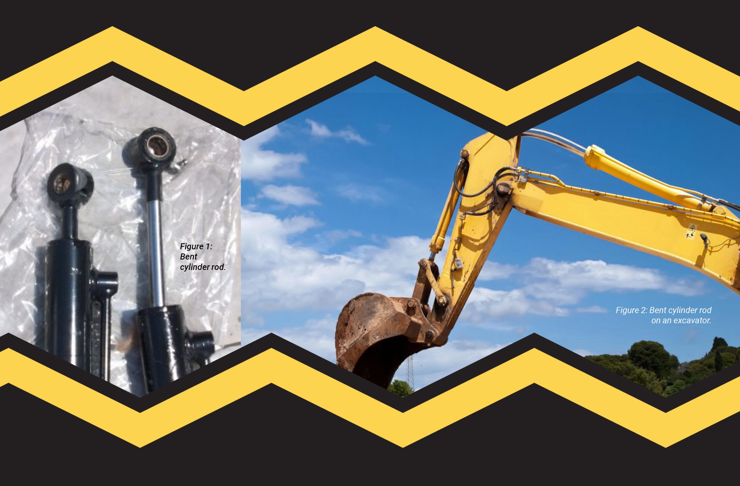
During extension, misaligned cylinders tend to cock, bind, seize, wear, and leak, particularly near the end of the stroke when the cylinder is fully extended, as shown in figure 1. Overloaded cylinders are more likely to become misaligned during normal operation. Long cylinders tend to become misaligned because they sag. This requires that the head end of the cylinder and the rod itself be provided additional support that is spaced out as the rod extends from the cylinder. Ladder trucks and other equipment that extend booms with long-stroke cylinders require this type of additional support.
A cylinder with a bent cylinder rod will also misalign itself because the force is not exerted on
the centerline of the rod. If the rod is misaligned, it tends to bend as the rod extends, as shown in figure 2. Another condition that may cause the cylinder rod to bend is lack of lubrication at the rod eye, causing the rod eye to seize at the pin. When the pin turns as the cylinder is extended, it can bend the rod next to the eye and cause it to break. This is a lubrication maintenance problem. Whatever the cause of misalignment, side-loading will cause the rod bearing in the head end of the cylinder to wear “out of round,” causing the cylinder to leak at the rod seal. This is not a reasonable wear condition for a cylinder.
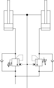
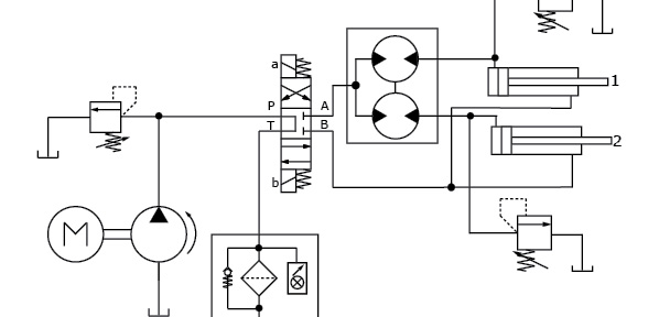
Figure 3: Tandem-mounted cylinders with counterbalance valves.
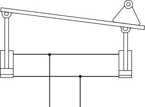
Figure 4: Tandem-mounted cylinders supporting an uneven load.
If two cylinders are connected by a machine member (crane boom or a loader bucket) such that they are mechanically linked, then they will have a tendency to bind or cock because the loading on the cylinders isn’t equal. This is likely to happen when each cylinder is equipped with a counterbalance valve to prevent the load from dropping, but the valves open at different set points (figure 3).
Misalignment of two cylinders that receive fluid from a common source can also occur if the load is not equally distributed to each cylinder (figure 4). For example, on a garbage truck, if two cylinders that compact the load from each side of the body unit encounter a solid object (e.g., a car engine) on one side, the sweep blade will be twisted as the side under load stops and the side without a load moves forward. A problem of this type is aggravated if the relief valve pressure has been increased to compact bigger loads. In severe cases, the cylinders may break loose or damage the compactor body.
A cylinder rod will leave telltale signs of misalignment, including scuff marks that show on one side of the rod when it is extended, a bent cylinder rod, and uneven wear side to side in the rod-eye and cap-end clevis. This would not include oval-shaped eyes that wear straight across the pin, which is caused by a lack of lubrication or extended use. Another way to detect misalignment is to watch the cylinder as it extends under load to see if it cocks and bows to one side when it stalls near the end of the extension stroke.
Misalignment can cause the piston to cock and gall the cylinder tube I.D. When the cylinder rod cocks, rather than riding smoothly in the bore, the piston is thrust against one side of the bore, causing metal-to-metal contact. Continued operation galls the cylinder bore and wears the piston on one side. Boring, or at least honing, is required to rebuild the cylinder, and piston replacement may be necessary.
When a cylinder is installed, the cylinder body and rod should be perpendicular to the clevis pins. The pins should be parallel to each other. The cylinder should also be parallel to the arc of travel in pivoting applications. A swivel rod-eye (figure 5) may be used to minimize any side loading to accommodate unavoidable “misalignment” between the cylinder rod and the driven object.
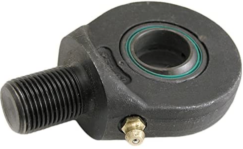
Figure 5: Swivel rod-eye.
TEST YOUR SKILLS
1. Under which condition would a side-loaded cylinder show the most misalignment
(Position – Stroke)?
A. Retracted – no load.
B. Mid-stroke – extending.
C. Mid-stroke – retracting.
D. End of stroke – extending.
E. End of stroke – retracting.
2.Rod cocking” from misalignment or over extension can cause the cylinder rod to:
A. gall.
B. become dented.
C. seize.
D. retract.
E. stretch.
1.d and 2.a.See the Solutions
Share this information.
Related Posts

The Function of Fluids
Understand the Function of Hydraulic Components in Circuits: The Application of Pumps and Intensifiers
Test Your Skills: Application of Proportional Valves

Test Your Skills: Considering Component Capability
Test Your Skills: Replacing Hydraulic Valves
Test Your Skills: Types and Applications of Compressors
Sponsor

Sponsors