Outside the Box: Rethinking the Traditional Reservoir

This article will take a look at three alternatives to the traditional reservoir. First, we will look at a reservoir by Price Engineering that takes an entirely different approach to the use of the reservoir. Second, we will look at a Cylindrical Reservoir that was designed for a more efficient removal of contamination from the fluid. Last, we will look at a new concept in reservoirs, designed and patented by Smart Reservoir.
We learned in our hydraulics 101 course that there are four primary functions of a reservoir. First, of course, is to store the fluid. Second is to allow enough time for the air to escape. Third is to allow enough time for the particulate matter to settle out. And fourth is to allow a certain amount of cooling to take place.
Studies have shown that it takes approximately two minutes for the air to escape and for the particulate matter to settle out. That is the reason for the rule of thumb that the reservoir capacity should be two to three times the average pump flow. The theory is that the fluid will be able to reside in the reservoir for two to three minutes, allowing it time to give up its air, give up its particulate, and give up its heat.
There are some aspects of the traditional, rectangular reservoir that need to be evaluated to see if they really have value. As stated earlier, the fluid is intended to remain in the reservoir for at least two minutes while the particulate settles out. The reality is that, in most rectangular reservoirs, the fluid tends to create its own direct path from the inlet to the outlet. This causes a large percentage of the fluid to simply swirl around inside the reservoir and not be drawn out into the system. Much of the fluid remains in the reservoir, and the working fluid is not refreshed. The swirling action is relatively gentle, and so the fluid has the opportunity to give up its air and its particulate matter.
This raises the question about where the particulate settles. It settles onto the bottom of the tank and collects around the baffles and braces. These particles are separated from the fluid stream, but only until there is some disturbance in flow. This could be from jostling, the return flow from a cylinder with a large differential area, or the draining of an accumulator. The disturbance could send a cloud of material into the stream where it can be drawn out into the pump. Ideally, there is a maintenance program that schedules a periodic cleanout of the tank, but that is not usually the case. The reservoir is typically cleaned only when there has been some other catastrophic event that necessitates the draining of the reservoir.
Another aspect is heat removal. There are formulas for calculating the heat transfer through the walls of a reservoir, but the fact is that the transfer is usually quite small in relation to the normal requirements of the system. Hydraulic fluid has a relatively high specific heat. It does not like to take on heat, and it does not like to give it up once it gets it. The heat-carrying molecules in the center of the tank are insulated from the outside wall by all the other molecules that are between it and the wall of the tank. Once the heat gets to the outside wall, it still has to pass through the wall, which is usually made of carbon steel, which itself has a relatively high specific heat. Many designers no longer include the cooling capacity of the reservoir in the calculations for sizing a heat exchanger.
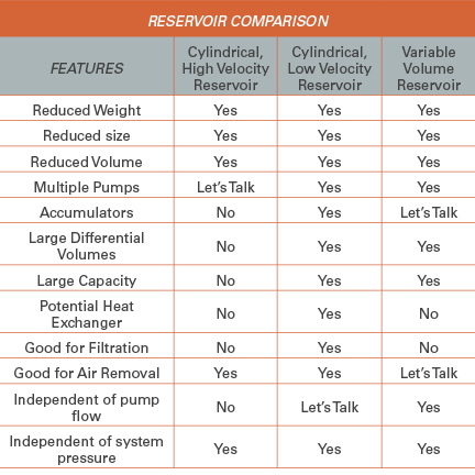
The reservoir design by Price Engineering uses a concept patented by Vickers in 1999. The idea is that the removal of the particulate can be done with the filtration system in line. The removal of heat can be handled by an external heat exchanger. That leaves only the removal of the air and the storage of the fluid to be the function of the reservoir. The reservoirs that they produce are cylindrical in shape and are amazingly small in relation to the average pump flows. A typical reservoir consists of a cylinder with two chambers, separated by a horizontal plate. The plate has a hole in the center, which provides a passageway from the lower into the upper chamber. The return fluid enters the reservoir tangentially to the cylinder and below the horizontal plate. The exit port to the pump is opposite the inlet and also is tangential to the cylinder. The relatively small reservoir forces the fluid to travel at very high velocity around the internal circumference of the cylinder. The centrifugal force pushes the dense hydraulic fluid against the wall and squeezes the lighter air bubbles toward the center of the rotating liquid. The small bubbles combine to make bigger bubbles that escape into the upper chamber and out the vent. The high-velocity fluid traveling around the internal circumference of the cylinder produces a positive pressure at the pump supply port.
The major advantage of this cylindrical reservoir is that it reduces the size of the reservoir to a fraction of the traditional type. For example, with an average pump flow of 75 lpm, a reservoir of only 5 liters is required. For the equipment designer, this means that much less real estate is required. It also means that there is much less weight to be carried, less fluid needs to be purchased, and that an oil spill will have a much lower environmental impact.
A characteristic of this design is that the pump flow needs to be relatively constant and to be within parameters that allow the proper velocity of fluid into and out of the reservoir. This tends to limit its use to systems with fixed displacement motors or cylinders with relatively small differential volumes. Systems that use pressure-compensated pumps, load-sensing pumps, accumulators, or high-ratio double-acting cylinders may not be good candidates for this type of reservoir. They are currently available in a variety of sizes for pump flows of up to 380 lpm.
There is no claim that these reservoirs are used for the removal of particulate matter or the removal of heat. However, preliminary studies have shown that, because the heated oil is traversing about 1 1/2 times around the inside wall of the reservoir before it is drawn out to the pump, the heat extraction is about 75% of what would be expected by a traditional reservoir.
The Cylindrical Reservoir uses some of the same principles as the one designed by Price Engineering. However, this cylindrical reservoir uses relatively low-velocity fluid in the return line to gently rotate the fluid within the cylinder wall. Centrifugal force separates the fluid into layers of density so the air and low-density particles move toward the center and the high-density contaminates move to the wall of the tank. This reservoir has a conical bottom to which is attached the intake to a kidney loop. The system allows the air to escape to the top of the fluid and out through the vent. The particulate settles down into the cone at the bottom. The cone is attached to the cylinder with a smooth seam, so there is no place for the contamination to collect. The flow through the cone into the kidney loop constantly washes away the particulate, so there is no settling of material at the bottom of the reservoir.
Like in the small cylindrical reservoir described earlier, the inlet and outlet are connected tangentially to the cylinder, opposite to each other, and at different levels. This arrangement, along with the normal vortex created by the flow into the kidney loop, causes the warm returning fluid to rotate around the inner wall of the cylinder several times before it exits the reservoir to the pump. Traveling slowly, the warm oil has a much greater chance to give up its heat through the reservoir wall. The heat removal is optimized when the device is made of aluminum, which has a much better capacity to dissipate heat than would carbon steel.
There are some important characteristics of this particular design. The reservoir is not being used for an extended dwell time for particulate and air to be removed. This is done dynamically rather than passively and reduces the amount of fluid required. A cylindrical reservoir has a smaller footprint than a rectangular reservoir of the same volume. Also, a cylindrical shape has greater structural integrity than a rectangular box and therefore can be made out of thinner material. This reservoir is not limited to a consistent return line flow in order to maintain the gentle vortex in the center. The fluid drawn into the kidney loop naturally produces a gentle spinning motion within the reservoir even if there is no return line flow. There is no need for the scheduled cleanout of the reservoir. It may be that the heat exchanger can be reduced in size or eliminated altogether.
As in the cylindrical reservoir that uses high velocity, with the Variable Volume Reservoir (VVR), it is assumed that the filtration and heat exchange will occur as a separate part of the circuit. Otherwise, the VVR is quite different. Both of the cylindrical reservoirs are vented to atmosphere. The VVR is a completely closed system. It consists of a bladder that is spring offset in a collapsed state. When it is commissioned, all the air is vented out and then the bladder is sealed. The advantage to this is that the reservoir does not breathe. It does not draw in moisture or dirt, adding to the life of the oil by reducing oxidation. The volume of the reservoir is determined by the differential volume of the actuators and the thermal expansion that may occur. If the actuators are hydraulic motors, double rod cylinders, or cylinders in series opposing one another as in a steering system, there is no differential volume and the VVR only needs to be sized to accommodate thermal expansion. The size of the reservoir is totally independent of the pump flow. Because it only sees return line flow, it is also totally independent of system pressure.
At first it appears that a system using the VVR is very similar to a hydrostatic transmission in that the return flow is directed to the suction line of the pump. The difference is that there can be multiple pumps supplying multiple actuators.
If all the cylinders are extended and the hydraulic fluid is cool, the reservoir is in a spring offset, relaxed state. As the cylinders retract and the temperature increases, the additional fluid in the return line causes the bladder to expand against the spring. This produces a positive pressure in the reservoir between 1 and 9 psi.
It is important to note that the reservoir does not see the rush of the return line fluid. It only sees the differential volume in the return line. Consequently, the fluid in the reservoir is relatively quiescent. Any air in the system rises to the top and is not drawn back into the fluid stream as the bladder contracts and expands. The positive pressure in the reservoir reduces the possibility of cavitation at the pump and allows the pump to be set at a substantially higher elevation than the reservoir.
The VVR is currently available in three different sizes: 7 L, 14 L, and 27 L. When choosing a reservoir for an application, approximately 75% of the capacity is reserved for the differential volume of the actuators. The remaining 25% is for potential thermal expansion. If greater volumes are required, multiple reservoirs can be mounted together in series on a manifold.
For more information: This article is based on a presentation at the 2013 Fluid Power Systems Conference held in Rosemont, Ill., from November 19-21, 2013.
Share this information.
Related Posts


Sponsor

Sponsors